Measuring the Usefulness of Fixtures for Hybrid Process Planning
|
Dept. of Mechanical Engineering and Institute for Systems Research University of Maryland, College Park, MD bsundar@eng.umd.edu |
Dept. of Computer Science and Institute for Systems Research University of Maryland, College Park, MD elin@cs.umd.edu |
|
Associate Director, CIM Laboratory Dept. of Mechanical Engineering and Institute for Systems Research University of Maryland, College Park, MD jwh2@eng.umd.edu |
Director, CIM Laboratory Dept. of Computer Science and Institute for Systems Research University of Maryland, College Park, MD nau@cs.umd.edu |
Abstract: This paper describes a usefulness measure that supports ongoing work on a hybrid process planning approach that combines the best characteristics of both variant and generative process planning while avoiding their worst limitations. To specify the fixtures needed by a process plan for a new design, the hybrid approach must identify existing designs and process plans that have fixtures that can hold the new design. Because traditional geometric similarity measures are inadequate, we have developed a new fixture-based usefulness measure.
Introduction: Developing successful generative process planners for complex machined parts is a difficult challenge. Although researchers have developed generative techniques for process selection, they have been less successful at developing generative techniques for selecting the fixtures needed to complete the process plan. To address this problem, we are developing a new hybrid approach to process planning, that combines both generative and variant aspects.
We believe that while a generative planner is a better approach for creating a preliminary process plan, a variant approach is a very useful technique for completing the process plan and adding the necessary details (such as fixturing). Thus, we are beginning with a successful generative process planning approach and adding a variant approach for fixture planning. The fixture planning approach must identify designs and process plans that have fixtures that can hold the new design. We have developed an approach for defining a usefulness measure that explicitly reflects fixture usefulness.
This paper gives a summary of our work. For further details the reader is referred to [1].
Background: A process plan describes the steps necessary to manufacture a product. When done manually, process planning is a subjective and time-consuming procedure, and it requires extensive manufacturing knowledge about manufacturing capabilities, tools, fixtures, materials, costs, and machine availability. In addition, the process planner must carefully document the plan using standard notation and forms.
Computer-aided process planning (CAPP) software systems automate many functions, which reduces the chance of error, and the process planner can work more quickly. In process planning practice, variant techniques are the tools of choice: they currently support almost all practical implementations of computer-aided process planning.
Another important approach is generative process planning, which attempts to synthesize a process plan directly for a new design. However, generative process planning has unfortunately proved quite difficult. As a result, most existing systems work only in restricted domains.
Finally, hybrid process planning approaches attempt to exploit knowledge in existing plans while generating a process plan for a new design. Though some approaches have been proposed, researchers have not yet developed comprehensive solutions.
As mentioned before, variant techniques are the tools of choice: they currently support almost all practical implementations of computer-aided process planning. Variant process planners are commercially available but have some limitations due to part mix changes, out-of-date process plans, and wrong batch sizes.
Typically, variant process planning is based on the use of the Group Technology coding schemes [2]. Typical schemes include DCLASS [3], MICLASS [4], and OPITZ [5]. Also see, for example, Chang & Wysk [6] and Bedworth et al. [7]. In each case the first step captures a new product's critical design and manufacturing attributes in an alphanumeric string, or GT code. The second step groups products with similar GT codes into product families. See, for example, the parts coding and classification analysis (PCA) approach [8].
The variant approach then proceeds as follows: Given a new design D for which a process plan is needed, the process engineer first determines a GT code for D, and then uses this code as an index into a database to retrieve a process plan P' for a design D' similar to D. Once this is done, the process engineer modifies the retrieved process plan manually to produce a plan P for the design D. Iyer & Nagi [9, 10] describe a sophisticated GT code-based search. Although GT code-based design similarity measures are useful for finding generally similar designs, these measures cannot be precise enough for process planning since there is no explicit link between process plans and the calculated GT codes.
Another possible basis for classifying designs is to use geometric properties of solid and CAD models. Most of today's CAD/CAM systems use either constructive or boundary models to represent solids. However, there exist no methods to compute a unique CSG representation, the CSG primitives do not necessarily correspond to manufacturing features, and, as far as we know, no methods to measure similarity on the basis of CSG trees currently exist.
Sun et al. [11] have described a similarity measure for solids based on properties of a boundary representation. However, the method works only with polyhedral objects. Moreover, the method does not incorporate (or reflect) manufacturing considerations, such as approachability, fixturing, and operation interference; and we do not see any obvious way to add them.
To overcome some limitations of such similarity measures, Singh [12, 13] has developed plan-based design similarity measures that explicitly incorporate process plan similarity by mapping design attributes into process plan characteristics. This yields measurements of similarity that are more accurate and more relevant to process planning.
Generative process planners would be ideal but they are quite difficult to develop. Given a new design D for which a process plan is needed, a generative process planning system attempts to synthesize a process plan directly for D. For machined parts, the typical approach is to do the planning on a feature-by-feature basis by retrieving candidate processes from the manufacturing knowledge repository, selecting the feasible processes on the basis of geometric and manufacturing-related constraints, and combining the chosen processes in a proper sequence.
A great deal of research has been done on generative approaches, and a number of experimental systems have been developed for various aspects of process planning [14, 15, 16, 17]. However, generative process planning has unfortunately proved quite difficult. Difficulties arise from interaction among various aspects of the problem, such as workpiece fixturing, process selection, and process sequencing. As a result, most existing systems work only in restricted domains. Although one generative system, the PART system [18], is being marketed commercially, generative systems have not really achieved significant industrial use. For a more detailed survey of variant and generative approaches, see [19, 20].
Hybrid process planning would combine the best characteristics of both variant and generative process planning while avoiding their worst limitations. A hybrid process planning approach attempts to exploit knowledge in existing plans while generating a process plan for a new design. Though some approaches have been proposed, researchers have not yet developed comprehensive solutions. Park et al. [21] describe an approach for acquiring knowledge useful for generating process plans, storing the knowledge as a schema, and then seeking and completing a schema with the same collection of features to construct a valid plan. Marefat and Britanik [22] propose a hybrid approach that captures plan knowledge that specifies the processes necessary to make a certain feature (with a specific size, hardness, surface finish, and tolerances). Planning decomposes a design by generating subplans for each feature independently and then searching the old subplans for the one that makes a feature that is most similar to the new design's feature. Lu et al. [23] describe a case-based approach that employs a hierarchical, feature-based representation of a design's shape, material, and precision and calculates a similarity measure that weights the similarity of these attributes.
As these examples show, the existing hybrid approaches have limited capabilities. A robust hybrid approach must consider feature interactions, precedence constraints, tolerances, and other critical design information that impact process planning. In addition it must consider how to store, classify, and retrieve useful design and process planning information. Finally, process planning should include fixture planning.
In machining, an important part of process planning is fixture planning: determining the fixtures that hold, locate, and support a workpiece in a particular setup and provide a means to reference and align the cutting tool to the workpiece. Proper location of the workpiece is essential to ensure accuracy and repeatability of the machining process [24].
Fixture planning is an important issue in small-batch manufacturing, which requires the flexibility of modular fixtures. While many areas have been explored to improve the cost-effectiveness of a manufacturing activity, none have as dramatic an impact on productivity as workholding practice [25]. Like process planning in general, identifying a good fixture for a given operation is a difficult task. Fixture planning is difficult because there are many different types of fixtures and fixture elements, and the fixture has to satisfy many constraints on stability, location, restraint, accessibility, and cost.
Process planning and fixture planning are two problems that have been addressed separately, but they have a significant effect on each other. Many researchers have attacked the problem of automatic fixture design and the integration of fixture planning and process planning. Previous research has focused on mathematical solutions for locating and holding a part and on expert systems and computer-aided fixture-planning routines. See Trappey & Liu [26], Chang [27], Fuh et al. [28], Yue & Murray [17], Kumar et al. [29], Darvishi et al. [30], and Chou et al. [31] for some approaches and additional references on automatic fixture design.
Hybrid Process Planning: This section briefly describes our hybrid approach to process planning. This approach attempts to combine the best characteristics of both variant and generative process planning while avoiding the worst limitations of each.
In a previous paper [32], we had proposed a hybrid process planner that first decomposed a design into independent collections of features and then searched for partial process plans that would create each collection. After this variant procedure, the approach then used a generative procedure that would combine and modify the partial plans to create a final plan. Since then, our work has proceeded and we have revised various aspects of this approach. This paper describes an approach that reflects our more recent ideas.
 |
|
 |
|
|
|
|
|
| ||
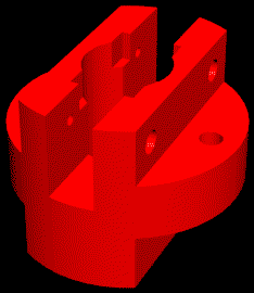
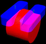
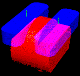
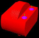
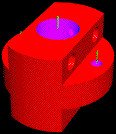
Specifically, we believe that, in most cases, a generative planner is a better approach for creating a preliminary process plan. A variant approach is a very useful technique, however, for completing the process plan and adding the necessary details (like fixturing). Moreover, geometric similarity measures are not as appropriate as asymmetric usefulness measures for identifying existing process plans that could be used to add these details. Consider the fixtures needed for the designs shown in Figure 1, for example. Almost any fixture for design D1 could be used for design D2 but few fixtures for the second design could be used for the first design due to first design's complexity and the additional constraints that the complexity adds to the fixture planning problem. A symmetric, geometric measure could not capture this fact.
The proposed hybrid process planning approach follows. It extends the generative approach that Gupta et al. [16] describe. After using that approach for process selection, it employs a variant procedure to select fixtures, which completes the process plan. We assume that the proposed design is available as a solid model, along with the tolerance and surface finish information as attributes of various faces of the solid model. We assume that we have information about the available machining operations, including the process capabilities, dimensional constraints, etc.
In a machining operation, a cutting tool is swept along a trajectory, and material is removed by the motion of the tool relative to the current workpiece. The volume resulting from a machining operation is called a machining feature. A machining feature corresponds to a single machining operation made on one machine setup. Each machining feature has a single approach direction (or orientation) for the tool.
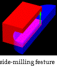
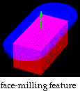
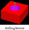
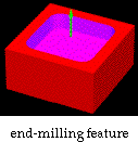
Specifically, features are parameterized solids that correspond to various types of machining operations on a 3-axis machining center: side-milling, face-milling, end-milling, and drilling. The most complicated of these features is the end-milling feature, which can be an arbitrary swept profile. Here are some examples of the features:
 |
 |
 |
 |
|
| |||
We represent a design as a collection of machining features. Using the F-Rex feature extractor developed by Regli et al. [33, 34], we can identify the volumetric machining features and build the set of all potential machining features by identifying various features that can be used to create the part from the stock. Each of these features represents a different possible machining operation which can be used to create various surfaces of the part.
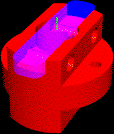
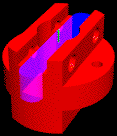
Given this feature-based representation of the design, there may be, in general, several alternative representations of the design as different collections of machinable features, corresponding to different ways to machine the part. Each of these collections of machinable features is called a Feature-Based Model (FBM). For example, the collection of machining features in Figure 4 is an FBM for the socket shown in Figure 3.
 |
       |
|
|
|
|
| |
Our approach involves generating and examining alternative FBMs, as follows:
This hybrid approach will have many advantages: It will extend the design loop to incorporate manufacturability analysis in a system that can be used once the geometry and tolerances have been specified. This will help create designs that not only satisfy the functional requirements but also are easy to manufacture. This approach includes sophisticated feature recognition and plan-based design evaluation in an integrated methodology. The approach is based on theoretical foundations which enable us to make rigorous statements about its soundness, completeness, efficiency, and robustness.
This hybrid approach will extend the generative approach, which is limited by the rules that capture the expert knowledge needed to create a process plan, by implicitly using the expert knowledge about fixturing that resides in the existing process plans. In addition, the variant fixture planning approach avoids checking the feasibility of each existing fixture and instead identifies the most promising setups with a usefulness measure.
Fixture Selection: Consider the fixture planning step, which must design a fixture for each setup. A setup is a set of consecutive operations that we would like to perform in the same fixture. Our approach will try to exploit the knowledge that existing process plans capture. We do not want to check each and every fixture that has been used in the past. Calculating each fixture's feasibility and then determining the necessary modifications for infeasible fixtures would require too much effort. Instead, we want to search quickly for the most promising setups that will have the most useful fixtures. So we will search the existing designs for process plans that contain fixtures that could be used for the new design's process plan.
This requires a database of existing designs. The database must include each design's process plan, which specifies a sequence of setups, the machining operations within each setup, and the fixture used in each setup. In addition, the database must contain a sequence of solid models that describe the workpiece before each successive setup, ending with the completed design. (Alternatively, the database could contain a solid model for the stock and solid models for each machining feature. From this one could derive the solid model for each successive workpiece.)
For each setup in the new design's process plan, we must identify an existing setup whose fixture can be used for the new setup. If necessary, the old fixture will be modified to make it feasible for the new setup. We will verify the fixture by first determining if the fixture can geometrically locate and constrain the workpiece in the absence of cutting forces and then determining if the part will lose contact with the fixture during the machining operations [28].
More formally, we are given a new design D and an incomplete process plan for D. The process plan specifies a sequence of setups and the machining operations to be performed in each setup. In addition, we are given a set D of existing designs with process plans. Each existing process plan specifies a sequence of setups, the machining operations to be performed in each setup, and the fixture for each setup. For a setup S in the process plan for D, we must find a design D' in D whose process plan contains a setup S' that uses a fixture that could be used for S. The next section describes an approach for defining a usefulness measure that can be used to identify the most promising setup S'.
Such a usefulness measure should have the following characteristics:
The remainder of this paper describes in more detail an approach for defining a usefulness measure that incorporates fixture usefulness information.
Approach: This section describes a three-step approach for developing a fixture-based usefulness measure. The measure will have the previously described desired characteristics. The measure calculates the usefulness of one setup for another. The approach includes a fixture usefulness measure and mapping functions that describe the correlation of the setup attributes and the fixture characteristics. These functions will incorporate local manufacturing characteristics and priorities.
Ideally, a setup's usefulness should equal its fixture's usefulness. Within a given manufacturing enterprise, it should be possible to determine (at least approximately) how the setup attributes impact the important fixture characteristics. Thus, the fixture usefulness measure (a function of the fixture characteristics) can be a function of the setup attributes, and this yields the usefulness measure.
This approach does not require any particular fixture, process plan, or design specification. The process planner can select and define any type or number of attributes that reflect local manufacturing characteristics and priorities. The process planner can specify any appropriate fixture usefulness measure. This measure should be a consistent, precise function of selected attributes.
However, the approach does require the planner to correlate setup attributes and fixture characteristics and to define mapping functions that describe these correlations. These functions can take any form and may approximate the correlations. They are not rules that completely construct a fixture. Instead, they describe how the selected design and process plan attributes affect the selected fixture characteristics.
Let us say that any fixture F has a set of n characteristics, so F = (c1, c2, ..., cn). A setup S has a set of m attributes, so S = (s1, s2, ..., sm). Then the steps are as follows:
This general approach can be applied to any class of designs and fixtures if one can define the fixture usefulness measure and the mappings. For more details and an example, the reader is referred to [1].
Example: Note that the example presented here illustrates the approach for defining a usefulness measure and is not intended to be a perfect measure, since it ignores some issues that affect fixture planning. Our research continues to develop more sophisticated measures for fixture planning in specific manufacturing domains.
The designs under consideration are prismatic parts to be machined on a vertical machining center. Each setup includes one or more machining operations performed from above. We know the geometry and topology of the initial workpiece, the features to be machined, the geometry and topology of the resulting workpiece, and the cutting forces generated during the machining operations [35].
The machine table has a grid of holes, and the fixtures are a collection of general-purpose components to locate the workpiece and kinematically restrain the part. For an existing design and process plan, a setup's fixture specifies the type and location of the fixture's elements and the clamping forces. We assume that a fixture always has six locating pins (using the 3-2-1 locating principle) and three clamps.
 |
 |
|
|
|
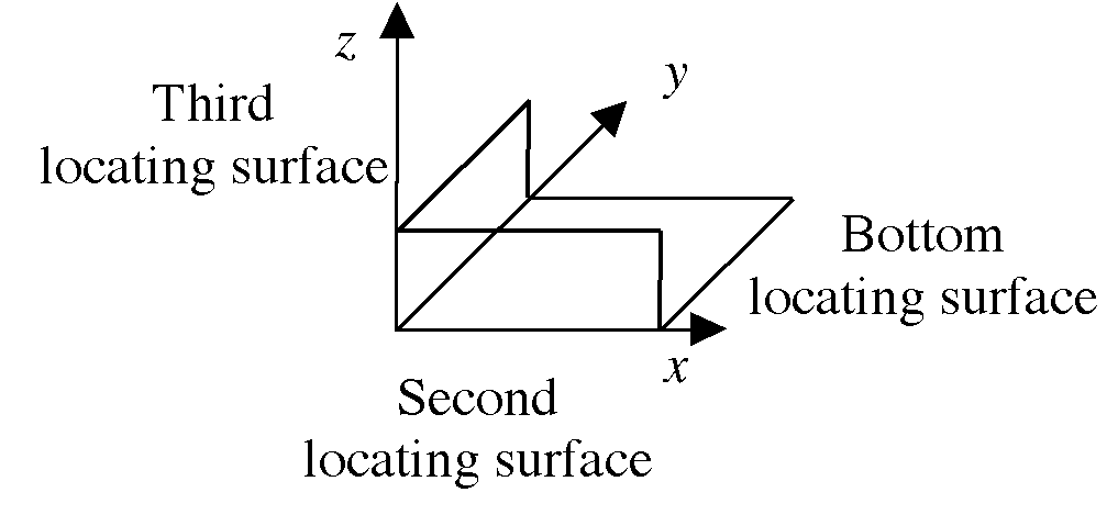
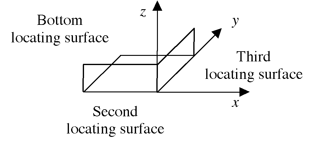
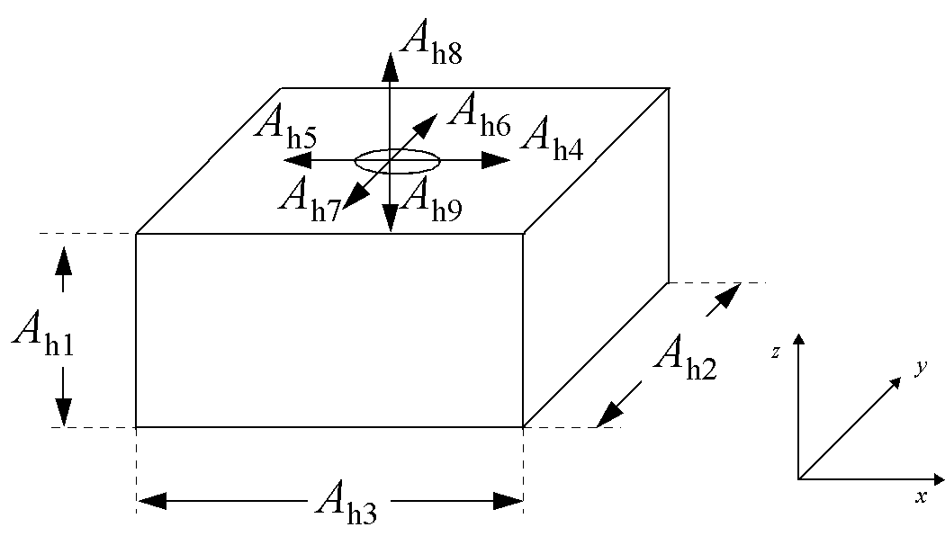
Let us define the fixture characteristics as follows: A fixture has six locating pins: three on the bottom locating surface, two on a side locating surface, and one on a third locating surface. For describing these points, we use the following local coordinate system: the bottom locating surface lies in Quadrant I (or II) of the xy plane, the second locating surface lies in the same quadrant of the xz plane, and the third locating surface lies in Quadrant I of the yz plane. Figure 4 illustrates Quadrant I and Quadrant II fixtures. We assume that the second locating surface is longer (in the x direction) than the third locating surface (in the y direction). A fixture has three clamps, one on the top of the part, one on the side opposite the second locating surface, and one on the side opposite the third locating surface. Each clamp has a clamping force. Let c1, c2, c3 be the vectors describing these clamp locations and k1, k2, k3 be the clamping forces in the -z, -y, and -x directions. Note that any vector ca = (ca1, ca2, ca3). If the fixture is in Quadrant II, then the third clamping force is in the +x direction.
 |
|
|
In [1] we describe how to define a two-dimensional fixture usefulness measure f(Fi, Sh) having the following properties:
This usefulness measure can be
used to compare fixtures relative to a given setup. If
f(F1, Sh) = (1, 0), f(F2, Sh) = (2, ![]() f),
and f(F3, Sh) = (3,
f),
and f(F3, Sh) = (3, ![]() p),
then we know that F1 is the most useful fixture for
Sh since it can be used without any
changes. However, F2 is more useful for Sh than F3 is, since F2 requires changes only to the clamping
forces while F3 requires changes to clamping and
locating points. If f(F4, Sh) = (2, 0.1
p),
then we know that F1 is the most useful fixture for
Sh since it can be used without any
changes. However, F2 is more useful for Sh than F3 is, since F2 requires changes only to the clamping
forces while F3 requires changes to clamping and
locating points. If f(F4, Sh) = (2, 0.1![]() f),
then we know that F4 is more useful for Sh than F2 is, since it requires less change than
F2. And if f(F5, Sh) = (3, 2
f),
then we know that F4 is more useful for Sh than F2 is, since it requires less change than
F2. And if f(F5, Sh) = (3, 2![]() p),
then we know that F5 is less useful for Sh than F3 is, since it requires more change than
F3.
p),
then we know that F5 is less useful for Sh than F3 is, since it requires more change than
F3.
In [1]we also describe how to use the usefulness measure f to define another usefulness measure h(Sk,Sh) having the following properties:
Note that this usefulness measure is a function of the setup attributes and yet reflects the fixture usefulness measure previously defined.
This measure allows us to
compare setups relative to another setup. If h(S1, S0) = (1, 0), h(S2, S0) = (2, ![]() f),
and h(S3, S0) = (3,
f),
and h(S3, S0) = (3, ![]() p),
then S1's fixture should be the most useful
fixture for S0 since it should require no changes.
However, S2's fixture should be more useful for
S0 than S3's fixture is, since S2's fixture should require changes only
to the clamping forces while S3's fixture should require changes to
clamping and locating points. If h(S4, S0) = (2, 0.1
p),
then S1's fixture should be the most useful
fixture for S0 since it should require no changes.
However, S2's fixture should be more useful for
S0 than S3's fixture is, since S2's fixture should require changes only
to the clamping forces while S3's fixture should require changes to
clamping and locating points. If h(S4, S0) = (2, 0.1![]() f),
then S4's fixture should be more useful for
S0 than S2's fixture is, since it should requires
less change. And if h(S5, S0) = (3, 2
f),
then S4's fixture should be more useful for
S0 than S2's fixture is, since it should requires
less change. And if h(S5, S0) = (3, 2![]() p),
then S5's fixture should be less useful for
S0 than S3's fixture is, since it requires more
change.
p),
then S5's fixture should be less useful for
S0 than S3's fixture is, since it requires more
change.
For a detailed example, the reader is referred to [1].
Summary and Conclusions: This paper describes a hybrid variant-generative process planning approach that will have the following advantages: It will extend the design loop to incorporate manufacturability analysis in a system that can be used once the geometry and tolerances have been specified. This approach includes sophisticated feature recognition and plan-based design evaluation in an integrated methodology. The approach is based on theoretical foundations which enable us to make rigorous statements about its soundness, completeness, efficiency, and robustness.
This hybrid approach extends the generative approach, which is limited by the rules that capture the expert knowledge needed to create a process plan, by implicitly using the expert knowledge about fixturing that resides in the existing process plans. In addition, the variant fixture planning approach avoids checking the feasibility of each existing fixture and instead identifies the most promising ones with a design usefulness measure.
We believe that, in most cases, a generative planner is a better approach for creating a preliminary process plan. A variant approach is a very useful technique, however, for completing the process plan and adding the necessary details (like fixturing). Moreover, geometric similarity measures are not as appropriate as asymmetric usefulness measures for identifying existing process plans that could be used to add these details.
The hybrid process planner requires a way to identify designs and process plans that may have useful fixtures. This paper describes an approach for defining a usefulness measure that explicitly reflects fixture usefulness. A specific example shows how one can use this approach to measure the usefulness of setups.
As a general method this usefulness approach could be applied to fixture planning in other domains. Future work will continue to develop the hybrid variant-generative process planner and address the related issues of design representation, process plan generation and evaluation, and fixture planning.
Acknowledgments: This work has been supported in part by NSF grant DMI 97-13718, ONR grant N00014-96-10888, and NSF grant EEC 94-02384. Any opinions, findings, and conclusions or recommendations expressed in this material are those of the authors and do not necessarily reflect the views of the sponsors.
References:
[1] S. Balasubramanian, A. Elinson, J. Herrmann, and D. Nau, "Fixture-Based Usefulness Measures for Hybrid Process Planning," Proceedings of the1998 ASME Design Engineering Technical Conference, Atlanta, September 1998.
[2] S. P. Mitrofanov, Scientific Principles of Group Technology, English Translation, National Library for Science and Technology, Washington, D.C., 1966.
[3] A. Bond and R. Jain, "The Formal Definition and Automatic Extraction of Group Technology Codes", Proc. ASME Computers in Engineering Conference, pp. 537-542, 1988.
[4] Organization for Industrial Research, "OIR Multi-M Code Book and Conventions," Waltham, Massachusetts, 1986.
[5] Opitz, H., A Classification to Describe Workpieces, Pergamon Press, Oxford, 1970.
[6] Chang, T.-C., and R.A. Wysk, An Introduction to Automated Process Planning, Prentice-Hall, Inc., Englewood Cliffs, New Jersey, 1985.
[7] Bedworth, David D., Mark R. Henderson, and Philip M. Wolfe, Computer-Integrated Design and Manufacturing, McGraw-Hill, Inc., Boston, 1991.
[8] Offodile, O.F., "Application of similarity coefficient method to parts coding and classification analysis in Group Technology," Journal of Manufacturing Systems, Volume 10, Number 6, pp. 442-448, 1991.
[9] S. Iyer and R. Nagi, "Identification of Similar Parts in Agile Manufacturing," in Concurrent Product Design, edited by R. Gadh (ASME, New York, 1994), 87-96.
[10] S. Iyer and R. Nagi, "Automated retrieval and ranking of similar parts in agile manufacturing," IIE Transactions, Volume 29, Number 10, pages 859-876, 1997.
[11] T.-L. Sun, C.-J. Su, R.J. Mayer, and R.A. Wysk. Shape similarity assessment of mechanical parts based on solid models. ASME Design Engineering Technical Conferences 83:2, 1995, pp. 953-962.
[12] Herrmann, Jeffrey W., and Gurdip Singh, "Design similarity measures for process planning and design evaluation," Technical Report 97-74, Institute for Systems Research, University of Maryland, College Park, 1997.
[13] Singh, Gurdip, A Plan-Based Design Similarity Approach for Hybrid Process Planning, M.S. Thesis 97-4, Institute for Systems Research, University of Maryland, College Park, 1997.
[14] M. Mäntylä, J. Opas, and J. Puhakka. Generative process planning of prismatic parts by feature relaxation, in B. Ravani, Ed., Proc. 15th ASME Design Automation Conf., ASME, 1989 pp. 49-60.
[15] S. Kambhampati, M. Cutkosky, J. Tenenbaum, and S. Lee. Integrating general purpose planners and specialized reasoners: case study of a hybrid planning architecture. IEEE Transactions on Systems, Man, and Cybernetics 23:6,1993.
[16] S. K. Gupta, D. S. Nau, W. C. Regli, and G. Zhang. A methodology for systematic generation and evaluation of alternative operation plans. In Jami Shah, Martti Mantyla, and Dana Nau, editors, Advances in Feature Based Manufacturing, pages 161--184. Elsevier/North Holland, 1994.
[17] Y., Yue and J. Murray, Workpiece selection and clamping of complex 2.5D components, in J. Shah, M. Mäntylä, and D. Nau, Eds., Advances in Feature Based Manufacturing, Elsevier, Amsterdam, 1994, pp. 185-214.
[18] R. Geelink, O. Salomons, F. van Slooten, F. van Houten, and H. Kals. Unified feature definition for feature based design and feature based manufacturing, in A. Busnaina, Ed., Computers in Engineering 1995, ASME, 1995, pp. 517-533.
[19] I. Ham., D. Marion., and J. Rubinovich, "Developing a Group Technology Coding and Classification Scheme," Industrial Engineering, Vol. 18, No. 7, pp. 90-97, 1986.
[20] I. Ham and S. Lu (1988), "Computer Aided Process Planning, the Present and Future," Annals of CIRP, 37(2).
[21] S.C. Park, M.T. Gervasio, M.J. Shaw, and G.F. DeJong, "Explanation-based learning for intelligent process planning," IEEE Transactions on Systems, Man, and Cybernetics, Volume 23, Number 6, pages 1597-1616, 1993.
[22] M. Marefat and J. Britanik, "Case-based process planning with hierarchical plan merging," IEEE, 1994.
[23] Lu, Wen F., Xiaoqing Frank Liu, Hsin-Chi Chang, and Lijun Dong, "Case retrieving for a responsive machining process planning system," Proceedings, NSF Design and Manufacturing Grantees Conference, Monterrey, Mexico, January 5-9, 1998.
[24] Hoffman, Edward G., "Fundamentals of Tool Design," Prentice-Hall, Inc., Englewood Cliffs, New Jersey, 1984.
[25] Hoffman, Edward G., "Modular Fixturing," Manufacturing Technology Press, Inc., Lake Geneva, Wisconsin, 1987.
[26] Trappey, J.C., and C.R. Liu, "A literature survey of fixture-design automation," International Journal of Advanced Manufacturing Ttechology, Volume 9, pages 240-255, 1990.
[27] Chang, Chao-Hwa, "Computer-assisted fixture planning for machining processes," Manufacturing Review, Volume 5, Number 1, pages 15-28, 1992.
[28] Fuh, Jerry Y.H., Chao-Hwa Chang, and Michael A. Melkanoff, "An integrated fixture planning and analysis system for machining processes," Robotics & Computer-Integrated Manufacturing, Volume 10, Number 5, pages 339-353, 1993.
[29] Kumar, Senthil A., Nee A.Y.C., and Prombanpong S., "Expert fixture-design system for an automated manufacturing environment," Computer-aided Design, Volume 24, Number 6, pages 317-326, 1992.
[30] Darvishi, A.R., Gill K.F., "Expert system rules for fixture design," International Journal of Production Research, Volume 28, Number 10, pages 1901-1920, 1990.
[31] Chou, Yon-Chun, R.A. Srinivas, and Sujit Saraf, "Automatic design of machining fixtures: conceptual design," International Journal of Advanced Manufacturing Technology, Volume 9, pages 3-12, 1994.
[32] A. Elinson, J.W. Herrmann, I. Minis, D. S. Nau, and G. Singh. Toward Hybrid Variant/Generative Process Planning, Design for Manufacturing Symposium, ASME Design Engineering Technical Conference, Sacramento, California, September 14-17, 1997.
[33] W. C. Regli, Satyandra K. Gupta, and D. S. Nau. Extracting alternative machining features: An algorithmic approach. Research in Engineering Design 7:3,1995, pp. 173-192.
[34] W. C. Regli, S. K. Gupta, and D. S. Nau. Toward multiprocessor feature recognition. Computer Aided Design, 1997, to appear.
[35] Gorczyca, Fryderyk E., Application of Metal Cutting Theory, Industrial Press Inc., New York, 1987.