![[Requirements 4]](images/requirements-fig4.gif)
Figure 1. Components of the Requirements Engineering Process
Requirements Engineering
Requirements engineering addresses the development and validation of methods for eliciting, representing, analyzing, and confirming system requirements and with methods for transforming requirements into specifications for design and implementation.
Figure 1. Components of the Requirements Engineering Process
The purpose of Figure 1 is to show how the requirments engineering and design engineering processes interact to produce precise specifications from which design alternatives can be generated. Combinations of informal requirements and domain knowledge are basic ingredients in creation of the design specification. Then, in turn, the design specification act as an initial point for the generation of design alternatives. Finally, the design alternatives are validated against the design specification.
Although no standard and generally agreed requirements engineering process exists, experience gathered from real-world projects indicates following activities are expected to be core activities in the process:
Requirements elicitation through which the requirements are discovered by consulting the stakeholders of the system to be developed.
Requirements analysis and negotiation through which requirements are analyzed in detail for conflict, ambiguities and inconsistencies and negotiated with stakeholders.
Requirements validation through which the requirements are checked for consistency and completeness.
Requirements documentation through which the requirements are maintained.
Development Pathway
Use cases --> Requirements --> Constraints/Objectives
In this section we are interested in:
      --------------------------------------------------------------------------
      Stage 1           Stage 2                       Stage 3
      --------------------------------------------------------------------------
      Use cases   -->   Semi-formal and       -->     Constraints and objectives
                        formal requirements           for optimization and
                                                      trade-off analysis.
      --------------------------------------------------------------------------
Constraints at Stage 3 emanate from rules associated with the execution of scenarios at Stage 1.
We will establish a number of development tracks:
![[Development Processes]](images/oo-development-process2.gif)
Figure 2. Development Tracks in Requirements Engineering
to clarify and manage use case modeling, domain analysis (i.e., domain-specific knowledge), interface specifications, architecture definition, and ongoing (iterative) development and management of the requirements and system design.
Requirements Elicitation through Goals and Scenarios
Before you can embark on the task of modeling and analyzing a system's structure and behavior, there needs to be a stage where you determine the goals of a project and relate them to measures of effectiveness. These related problems are resolved by analyzing the information available at the start of the engineering process (through goals and scenario analysis), and setting in place concurrent activities support development and analysis of the system requirements and models.
A scenario is an example (or fragment) of typical system usage, represented as a sequence of steps describing the intended interaction between a system and its environment to achieve some purpose. Scenarios are a useful and efficient way of helping project stakeholders articulate and refine their goals for the system, and validating and documenting system behavior and system requirements.
In the early stages of a project lifecycle, the construction of scenarios for how a hypothetical system might be used are sometimes easier to get than some goals which can only be made explicit after some deeper understanding of the system has been obtained.
Explicit representation of system properties is needed to enable the scenarios covering performance for acceptance test cases. Scenarios covering acceptable system performance reduce the need for fully-fledged system tests (expensive!).
Requirements describe the functional and behavioral properties of the system to be built.
Because most systems are multi-functional, many scenarios may be needed to describe the system's intended behavior completely. Input from multiple stakeholders heads to a shared view of the system goals.
![[Goals-Scenarios-Requirements]](images/uml-requirements.gif)
Most often an iterative procedure is needed to elicit, analyze, and clarify project scenarios and requirements. The key steps are as follows:
In an object-driven problem formulation, observations of scenario execution leads to the generation of requirements, which in turn, feed into the system behavior model. Scenarios and requirements are of equal importance.
![[Requirements: Fig 1]](images/requirements-fig1.gif)
Figure 4. Incremental Development of Requirements and the System Design
The adjacent schematic shows the ensuring incremental development of requirements and the system design. Both sides of this diagram should be equivalent.
Note. The triangular abstractions for requirements and design development indicate that "volume" of materials or development detail increases with each iteration of work. What this diagram doesn't show is that requirements come from a variety of internal and external sources. Internally, requirements will eminate from high-level decisions that constrain the space of possible design options, and requirements derived through engineering analyses. Externally, requirements will be bought into the project through adoption of technologies and reuse of previous work.
Requirements Acquisition vith Multiple Viewpoints
If "global reasoning in large and complex project development" is to occur with any assurance of quality, then a necessary prerequisite is requirements that capture the views and responsibilities of all parties involved (e.g., engineering, maintenance, production, business, customer ...... viewpoints). In fact, there would appear to be a direct correlation between completeness of requirements early in the project life-cycle, and the ability of project participants to make good decisions and handle conflict resolutions.
As we will see in the DEC case study problem below, ad hoc approaches to the collection of viewpoints often lead to skewed results. One problem is that in most projects the requirements engineer is not an expert in the application domain being addressed, and so many problems can be traced back to misunderstandings between the requirements/applications engineers, and implicit assumptions made by potential users/customers.
In an effort to overcome some of these problems, researchers (Kotonya, 1996) have recently derived formal structures for requirements engineering using viewpoints associated with the sources of requirements. The goal is to provide assistance in the organization and structuring of requirements, and to balance the need for preservation of multiple viewpoints during the system development on one hand, with the demands for consistency and coherence on the other hand. Three problems need to be addressed in order to implement a practical system:
At this point two general classes of requirements have been identified:
Direct viewpoints correspond to clients who receive services from the system and send data and control information to the system. In other words, they are the system's users and operators.
Indirect viewpoints have an interest in some or all of the services which are delivered by the system, but do not interact directly with it. Indirect viewpoints may generate requirements that constrain the services delivered to direct viewpoints (e.g., fire code regulations; design code requirements).
Figures 5 and 6 are taken from a paper by Kotonya and Sommerville (1996) and show a general viewpoints model, and a hierarchy of classes for viewpoints.
![[Requirements 6]](images/requirements-fig6.gif)
Figure 5. Process Model for View Oriented Requirements
![[Requirements 7]](images/requirements-fig7.gif)
Figure 6. Abstract Classes for Viewpoint Requirements
The first step in Figure 5 is identification of relevant viewpoints for a problem domain, and structuring them. Step two is requirements documentation (e.g., name, requirements, constraints ... and requirements source). The final step is specification of all requirements in an appropriate form. Appropriate notational forms include textual descriptions of requirements, design code equations, and system models.
The class hierarchy shown in Figure 6 is by no means generic, and each organization will need to generate a hierarchy appropriate to its organizational structure and project needs.
The combined purpose of a formal model to support systems viewpoints, and a class hierarchy of viewpoints, is analysis procedures that will establish correctness of the requirements, and expose conflicting requirements across all viewpoints.
Generation of Derived Requirements
One of the key purposes of engineering analysis is the assessment of performance functions for proposed systems. These performance functions are, in effect, derived requirements for expected system performance. See Figure 7.
![[Requirements 4]](images/requirements-fig5.gif)
Figure 7. Generation of Derived Requirements
Example. In NASA's Mission to Planet Earth Project, NASA generates a small set of primary requirements (i.e., less than 1000 requirements) and passes them onto Hughes, a NASA contractor.
![[Requirements 11]](images/requirements-fig11.gif)
With the primary requirements as input, Hughes derives a much larger set (e.g., tens-of-thousands) of requirements containing technical detail, system specifications etc...
Layers of Requirements
In large projects requirements may pass through several layers -- each new layer will add technical detail to the project specification. For example, in NASA's MTPE project, requirements are partitioned into four levels. They are:
The Level 1 requirements will be written by the Agency and passed onto the prime contractor. The prime contractor will {\tt derive} requirements for levels 2 to 4, adding technical details of requirements as appropriate.
The overall goal is to map requirements between different levels and development phases to minimize over/under design, and to be able to identify project items that will be affected by a project change.
Levels of Requirements Compliance
Requirements that:
Information requirements are not requirements per se; they are non-binding statements intended to influence the context, meaning, and understanding of other more important requirements. Among these levels, mandatory requirements are subject to the most review, with the degree of review adjusted accordingly for guidance requirements and information statements.
Similar hierarchies of requirements importance are found in optimization circles, where we speak of hard and soft constraints. Hard constraints are those that must be satisfied. Soft constraints are those that may be traded off with one another, and with design objectives.
Acquisition of Design Requirements
The three main activities that contribute to the generation of a requirements specification are:
Requirements elaboration is the task of eliciting necessary design requirements and then giving formal representation to them as constraints. This process:
Deriving requirements from an existing system, from the previous generation of the same engineering system, or via the synthetic analysis of the characteristics of a system.
Iterative refinement of a prototype (the final version of the prototype may serve as the requirements specification).
In this section we focus on techniques for requirements acquisition. The standard techniques include: (1) interviews and questionnaires, (2) survey of documents/existing systems, (3) analysis of working practice, and (4) observation.
Requirements Questionnaires
Good requirements are stimulated by answers to the following questions:
This approach to requirements acquisition is not without its limitations. One problem lies in the selection of questions ... we need to be very careful that all of the right questions are answered, and that the final product does not become skewed because the requirements acquisition phase failed to capture information from all of the important parties.
![[OO development]](images/oo-development.gif)
Figure 8. Operational Concept to Integrated Views for System Capability
In UML-driven development the generation of system requirements through use case modeling activities proceeds as follows:
Management of use cases should be viewed as akin to lifecycle management of requirements. Use cases need to be validated with users, and updated to mirror and reflect the changing needs of a project.
Click here for guidelines on creating domain models.
Click here for guidelines on developing use cases and use case diagrams.
Observations of scenario execution leads to the generation of requirements, which in turn, feed into the system behavior model.
![[OO Behavior]](images/oo-behavior2.gif)
Figure 9. Pathway from Use Cases to Simplfied Models of System Behavior
In an object-driven problem formulation, scenarios are represented as objects and operations that can be applied to the objects. The third element of scenarios are rules governing the pathway of behavior, perhaps governed by the logical relationship among data/information in the system.
Sequence Diagrams
By describing an interaction between a set of objects collaborating to achieve an operation, sequence diagrams show the internal dynamic workings of a use case scenario. Sequence diagrams enable designers to perform three key tasks:
One sequence diagram encompasses the basic and alternative courses of action within each use case. Sequence diagrams contain text for the use cases (shown down the left-hand side of the diagram), objects, messages and methods. The messages exchanged during the interaction explicitly appear on the diagram -- as shown in the diagram above. Objects participating in the collaboration are laid out along the horizontal axis. The vertical axis represents time.
If the "desired" and "modeled" behavior do not match, then the object classes and their state diagrams need to be re-engineered. Alternatively, the "desired" behavior may have been poorly specified and needs to be re-engineered.
Collaboration Diagrams
Collaboration diagrams tie object models to behavior models. However, unlike sequence diagrams, time is not represented on a separate axis. Instead, the collaborating objects are shown with relationships that play a role in the collaboration (this means that collaboration diagrams tend to look like class diagrams). Messages are placed on the relevant relationships and are annotated with a sequence number to replace the missing time.
Features of this Approach
Multiple iterations occur between developing the domain model and identifying and analyzing the use cases. Other iterations occur as well -- the static model gets refined incrementally during successive iterations through the dynamic model (composed of use cases and sequence diagrams) ... see figure XXX.
At each step in the design process, developers refer back to the requirements in some way. Traceability also refers to the tracking of objects from their role in system analysis, to system design, to system testing.
Constraints are things that must be done or, conversely, must be avoided (ref. LA, 1997, pg. 44). They can express relations, complex interactions, and dependencies among elements of a system. For example, in the simple UML diagram:
![[Requirements and Constraints]](images/system-constraints2.gif)
Figure 10. Constrained Relationshiup between Systems A and B
systems of type A are constrained to be connected to one or two instances of systems of type B . The adjacent diagram shows a close relationship between "requirements" and "constraints."
![[Requirements and Constraints]](images/system-constraints.gif)
Figure 11. Flowdown of Requirements and Constraints
Sometimes upper-level constraints will be decomposed into lower-level project requirements. For example, an external regulatory constraint (which can be viewed as a non-negotiable requirement) may trigger several lower level requirements that a project must fulfill. Conversely, upper-level requirements can become lower level constraints. For example, an external regulatory constraint may trigger a set of project requirements, which in turn, will trigger the need for lower-level constraints on system performance.
Dealing with Constraints in Design
Before constraints can be integrated into a process for systems design, it is important to consider the different ways in which constraints should be dealt with in design, Constraints can be classified according to the role they should play in trade-off studies:
Hard constraints are non-negotiable and cannot participate in trade-off analyses (e.g., in mechanical engineering design, the dynamial behavior of a mechanical mechanism is constrained to follow the laws of motion). Similarly, in the design of very-large scale integrated (VLSI) ciruits, a logic designer may begin with the constraint of using strictly AND, OR, and NOT gates to build a circuit.
Soft constraints, on the other hand, are not critical to system performance and can participate in trade-off studies.
Generally speaking, the number of constraints increases as a design evolves. A good design leaves sufficient options available in the final stages of development so that improvements and corrections can be made. A poor design pushes the designer into a corner where adjustments and tradeoffs are virtually impossible to make.
The most difficult constraints (or objectives) to deal with are those that are are continuous, have no optimal solution, but compete directly with other constraints (or objectives) for resources. In a product line of home computers for example, performance and features compete directly with cost. Designers must develop options that are technically noninferior in some areas and also non wasteful in others. The rules for dealing with these trade-offs are complex, interwined and imprecise.
In this course we define traceability as "any textual (or model or project) item which needs to be explicitly traced from another textual (or model or project) item in order to keep track of the dependencies between them. A traceability system can be formally defined as a semantic network in which nodes represent objects among which traceability is established through links of different types/strengths. This dependency-directed approach of maintaining consistency of design dates back at least to the work of Stallman and Sussman (Stallman, 1977).
Therefore, requirements traceability is an explicit tracing of requirements to other requirements, design elements, test requirements, and other supporting items such as design documentation .... Traceability mechanisms are important because they help to close major gaps in the development domain (e.g., mis-communication of data/information in team development).
Often the customer lacks the tools needed to generate system requirements in a complete and precise manner. If the systems engineer has to infer the customers needs, then inconsistencies with the customers real needs are likely. Traceability mechanisms help to close this gap.
The requirements generated by the customer are often incomplete -- hence, the systems designer must derive additional functions that describe what the system is supposed to do. Using traceability mechanisms to connect the customer to the designer helps to avoid gaps in intent.
Software component designer must often hypothesize the behavior of components they are implementing. Communication of high-level behavior and system functionality to developers of lower-level components/modules can be improved by providing traceability from the latter to the former.
Complex engineering systems (e.g., commercial aircraft or naval warship) may have hundreds-of-thousands, and possibly millions, of requirements, The tracing of requirements to details of the design (i.e., processes, activities, and components) is motivated by economics. Simply put, an error in the systems requirements document that remains undetected until the latter stages of project development is likely to be much more expensive to fix than one identified early on in a project.
Traceability also provides a means for guarding against under- and over-design.
For engineering systems development, design objects should be traceable back to the requirement(s) driving their need, and the functionality/behavior (i.e., use cases) required of the system.
Product-Related Traceability Links
Traceability mechanisms support the capture and usage of trace data (i.e., to document, parse, organize, edit, interlink, change, and manage requirements and traceability links between them.
![[Requirements: Fig 1]](images/requirements-fig2.gif)
Product-related traceability is (primarily) supported by two types of traceability link:
Ensure that requirements are satisfied by the system. Relationships between one or more design implementation objects and requirement objects verified by compliance verification procedures (CVPs). Uses include:
Help manage the dependencies among objects (typically at the same stage of development), often imposed by a constraint. Uses include:
These links are accomplished through connectivity of requirements to sets of system components that satisfy them. These links may be indirectly derived. For example, a design component may be linked to requirements the former satisfies. The design component, in turn, may become a system component....
For the "use case -- requirements -- system design" problem domain, traceability links can be partition into three categories:
Links are established from individual use cases forward to individual (or groups of) requirements. These links ensure that the system vision (as recorded in the use cases) is properly mapped to the system requirements. Links may also tie requirements back to the use cases from which they emanate. They allow for verification that the system meets the needs of the system users.
Tracing requirements in this way allows designers to answer two key questions. Looking forward, designers can see the pathway from "use cases" to "groups of requirements." Looking backward, designers can see the connection between a particular group of requirements and system functionality (as represented by use cases). We can say things like "requirement A-1 depends-on use case A."
Links are established from requirements forward to design elements that are built in response to requirements. Links may also be connected from design elements back to the requirements from which the element emanates.
Tracing requirements in this way allows designers to answer two key questions. Looking forward, designers can see how a requirement (or group of requirements) has actually been implemented in (and hopefully satisfied by) the design. Looking back, designers can see why a particular design element is needed.
Connecting system modeling viewpoints enables designers to understand how trade-offs required for one discipline may impact other disciplines.
Process-Related Traceability Links
These links describe the history of actions taken in the process itself, including evolves-to (i.e., temporal evolution design objects) and rationale (i.e., rationale for the action is captured by a higher-level object).
Document the input-output relationships of actions leading from existing object(s) to new modified object(s). Uses include:
Represent the rational behind objects or document the reasons for evolutionary steps. Uses include:
Link Semantics
Consider the following relationship maintained in a traceability table:
REQUIREMENT ---- LINKED-TO ---- DESIGN object.
The semantics of a given linkage depends on who is interpreting the relationship. An end user may view the relationship as a means to identify a design component that is generated by a requirement. A designer may view the same linkage as providing information on the requirement/constraint that restricts the design object(s). The semantics associated with a linkage is guided by the reasoning that the user will be performing with the linkage.
Meta-Models for Requirements Traceability
The meta-model framework defines: (1) the language in which traceability models can be defined, (2) A set of reference traceability models which can be customized within the scope defined by the meta model; (3) A database (possibly distributed) of actual traces, recorded under the chosen models.
![[Traceability: Fig 1]](images/traceability-fig1.gif)
Each entity and link in the meta-model can be specialized and instantiated to create organizational and project-specific models. These models can be viewed as representing dimensions of traceability information, as shown in the adjacent table.
| |
|
| |
Rationale for design decisions. |
| |
Systems designer. |
| |
In the design documentation library or database. |
| |
Using tool A, B or C? Represented as a "Rational X justifies design decision Y" traceability link. |
| |
To facilitate understanding and communication with other developers, team members and so forth. |
| |
A the finalization of the design |
The dimensions of traceability information are as follows:
In the model, OBJECTS represent the inputs and outputs of the system development process. Examples of OBJECTS include:
      Requirements,
      Assumptions,
      Designs,
      System Components,
      Decisions,
      Rationale,
      Alternatives,
      Critical Success Factors.
OBJECTs represent the conceptual objects among which traceability is maintained. And they are created by specific tasks (e.g., design and analysis tasks).
Traceability across various objects is represented by TRACES-TO links (e.g., a DEPENDS-ON link between two objects, perhaps a REQUIREMENT and an ASSUMPTION, can be treated as a specialization of TRACES-TO).
All OBJECTS are documented by SOURCES, which may be physical media, such as documents, references to people or undocumented policies and procedures. Examples of SOURCES include:
      Requirements Specifications,
      Documents,
      Meeting Minutes,
      Design Documents,
STAKEHOLDERS manage SOURCES.
Low-End Users of Traceability
Industry experience indicates that low-end users of traceability tend to have problems that require less than about 1,000 requirements (viewed as a mandate from the project sponsors or for compliance with standards).
Users view traceability as a transformation of requirements documents to design. Hence, the main applications of traceability are: requirements decomposition, requirements allocation, compliance verification, change control.
![[Traceabilit: Fig 2]](images/traceability-fig2.gif)
Points to note are as follows:
Typically, low-end users lack support for capturing rationale for requirements issues and how they are resolved. Similarly, information also tends to be missing from the design and analysis phases of development.
High-End Users of Traceability
Industry experience indicates that high-end users of traceability tend to have problems that require, on average, about 10,000 requirements (viewed as a major opportunity for customer satisfaction and knowledge creation throughout the system lifecycle). They view traceability as an opportunity to increase the probability of producing a system that meets all customer requirements, is easier to maintain, and can be produced within cost and on schedule.
Due to the significant size and complexity of systems under consideration, high-end traceability employs much richer schemes of traceability (e.g., capture of discussion issues, decisions and rationale product-related and process-related dimensions) than their low-end counterparts. Problems associated with the former can be classified as follows:
Systems are created to satisfy organizational, stakeholder, operational and strategic needs.
System objectives must be justified by organizational needs. As part of the negotiation process among stakeholders, many trade-offs are made in deciding the scope and functionality of the system based upon their impact on critical success factors (CSFs) (or in GE nomenclature, measures of effectiveness).
Not all requirements are of equal significance or criticality -- high-end systems account for the relative importance of requirements in supporting the design process.
The specification, elaboration, decomposition, derivation and modification of OBJECTS (e.g., requirements, designs) generate issues or conflicts (due to differing interpretations, assumptions, interests, viewpoints and stakeholder objectives). Traceability pathways of rationale enable accountability (e.g., what changes have been made; why and how they were made), particularly to stakeholders not directly involved in creation of the requirement.
Information about how to resolve these issues must be maintained throughout the system lifecycle to the ensure customer requirements are understood and satisfied.
For example, various alternatives that address the resolution of issues are normally considered. Arguments for and against each alternative may be proposed.
A complete and detailed capture of rationale may be impractical due to the lack of tools. However, simple descriptions of rationale on which requirements or design are based may be recorded along with the assumptions behind them.
This term refers to the activity that creates artifacts, including implementation. Key elements are REQUIREMENTS that drive DESIGN, which in turn are based on mandates such as standards, policies or methods. Requirements are allocated to components.
Components are also organized into hierarchies and networks -- we would like some form of traceability to record relationships among components.
Compliance and verification procedures (CVPs) are developed to ensure that each requirement is satisfied (If a requirement cannot be tested, then by definition, it is no longer a requirement).
Note. Low-end requirements traceability tends to focus on items (3) and (4).
Fluctuating and Conflicting Requirements
Good requirements specifications provide stability in the midst of project change. One way that they provide stability is by acting as the project memory, since they stay constant as employees come and go, and as design changes occur. The key issue is not whether requirements will or can change, but how to control and manage their change. Fluctuating and conflicting requirements may be due to market impacts, company impacts and hidden impacts. The causes of each impact are as follows:
| |
|
| Customer |
|
| Technology |
|
| Regulations |
|
| |
|
| Approvals |
|
| Technology |
|
| |
|
| Implementors |
|
In systems engineering, the mechanism of changing requirements is the process of baseline control and configuration management.
Configuration Management
Requirements are an essential component of systems design because of their ability to provide stability to a project that is constantly in a flux of change. Sometimes the changes in requirements are planned, and sometimes they aren't. For example, a change in requirements can occur because the end users did not foresee all of the opportunities for a system's use. Other common reasons for change are revisions to the objectives of a program, advances in technology, budgetary changes, schedule changes, natural disasters, and so forth. Sometimes a requirement change is caused by the identification of an inadvertently overlooked constraint. When a contractor fails to meet a contractual/legal agreement, then such a realization can cause a chain of requirements to be invalidated.
Configuration management is the discipline of identifying selected elements of a system at discrete points in time for the purposes of systematically controlling changes to the configuration, and maintaining the integrity and traceability of the configuration throughout the system life cycle. Configuration management is composed of four parts:
Identification
Identification is the careful selection of all hardware and software items that control must be maintained over. Maintaining control means that at any point in time, you are able to report on what the system consists of, what changes are being proposed, what have been accomplished, and what effects (if any) these changes have had on the ability of the system to meet original requirements.
Baselines are established throughout the implementation process to provide increasing degrees of control as the system product matures.
Figure 15. System Life Cycle Baselines
Figure 15 shows that there are at least five logical points that can be used to establish baselines for the purposes of configuration management. They are:
Typically established at the conclusion of the functional requirements. The functional requirements document is written prior to the system requirements review (SRR), and in many cases provides the basis for a request for a proposal.
Normally established after the preliminary design review (PDR), and prior to the detailed design. It represents the point in the engineering design where required system performance has been allocated through the system specifications to specific hardware and software configuration items and subsystems.
Normally established following detailed design, and at the conclusion of critical design review (CDR). This is the baseline to which all subsequent hardware and software implementations must adhere.
Established prior to production. System and subsystem specifications, initial fabrication, system integration, and test and factory readiness are all complete.
This baseline is the basis for all continuing system maintenance and product improvement phases.
As each baseline is established, formal methods for control of changes to that baseline are also established (see configuration control below).
Configuration Control.
Configuration control is the formal set of policies and procedures for requesting, evaluating, and accepting (or rejecting) proposed changes, corrections, or waivers to a configuration item. Configuration control is maintained on the current baseline and all previous baselines. So, for example, a change to the physical hardware/software will result in changes to all supporting documentation as well.
Configuration auditing is the process of determining the extent to which the current configuration baseline conforms to the previous baseline, and to the original functional requirements (functional baseline).
This process involves verification and validation. Verification is the process of determining if the configuration items of a given baseline meet the requirements of the previous baseline. Validation is the process of determining if a given baseline still solves the intended problem. Validation involves traceability of a design to original requirements.
Status accounting is the administrative function that maintains a formal record of each configuration item, including their definition, change requests, change approvals, and progress towards implementation.
Change Control
Figure 16 is a flow-chart of activities in the evaluation of changes to a project's requirements.
Figure 16. Flow Chart of Decisions in Change Evaluation
Points to note about this chart are as follows:
Guidelines for Change Implementation
Here are some hints on how to implement changes in requirements:
Pre-planned Change versus Responsive Change
Monitoring Requirements Consistency Among Contractors
Many of today's projects are so large that they are broken down into components. Individual components may be handled by separate contractors who will have their own computer networks for the management of requirements. In this case traceability can be easily lost as requirements distribution and management over many groups or unrelated companies becomes virtually impossible.
Figure 17. Monitoring Requirements Distributed Among Contractors
The purpose of Figure 17 is to show that when requirements are distributed, an independent authority may be needed just to monitor and trace requirements across disconnected networks in different geographic locations.
This case study is based on an article by Hutchings and Knox (Hutchings, 1995), which documents the issues concerning cultural change when a company moves from a product requirements definition process to customer driven product development. The objective is to ensure customer satisfaction and business readiness before a line of code is written, an electronic circuit designed, or a service defined.
Problem Statement
In 1993 the Digital Equipment Corporation (DEC) sought to move from a technology-centric view of product development to a customer-centric view. Most important among these insights were the concept of ``whole products,'' which had the effect of broadening the requirements definition scope to include requirements for marketing massages, pricing, and packaging, as well as deployment and service scenarios.
Figure 18. Multiple View Product Development at DEC
Figure 18 shows that this move also required a shift in thinking about process, moving away from process as a series of sequenced procedures to one that describes a map of the product development terrain.
Need for Change
So why change? In an earlier review of business practices, DEC discovered that 40% of the requirements specified in the feasibility and requirements phase of the life-cycle were redefined at a later stage. As a result, DEC was forced to spend, on average, 50% more than initially budgeted.
The causes of requirements change included:
Best Practices
The same internal review also identified a number of best practices, namely:
New Requirements Management Process
A requirements management re-engineering team was formed in response to the data collected. Team members were from key organizations (hardware and software), and key functions (engineering, business and marketing).
The team adopted a Level 2 SEI/CMM requirements management model, where agreed-on requirements are managed and actually built into the product. However, since the issue of ``right requirements'' was found to be a root cause of requirements churn and schedule overrun as experienced in many of the product development efforts at DEC, a nine-step modified design process was developed. The steps are:
The outcome from this point can be points/strategies for market leverage.
An internal study found that while most projects were good at identifying their subsystem dependencies, the pathway from these dependencies to a ``dialogue for commitment'' was often lacking. Hence participants in a project sometimes had difficulty in understanding why they were supporting one another.
New requirements proposals should be accompanied by a detailed cost-benefit analysis.
While this list of steps might suggest sequential execution, in practice, there is a great deal of iteration and concurrency, as indicated by the big arrow in Figure 18.
Experiences with Pilot Implementation
Several problems were encountered with the pilot implementation:
How do we capture, represent and use knowledge through requirements engineering activities?
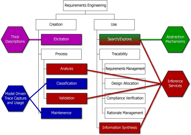
Figure 19. Requirements Engineering WBS and Industry Toolset Weakensses. (For details, see Ramesh and Jarke, 2001)
Specific Limitations of Present-Day Tools (Selberg, 2002)
Observations
The Semantic Web Layer Cake
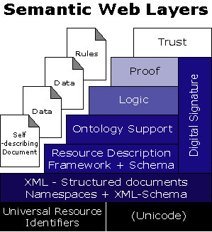
Figure 20. The Semantic Web Layer Cake (Berners-Lee, 2002). |
The Semantic Web is an extension of the current web.
|
Ingredients in the Semantic Web Infrastructure
The Semantic Web will be a composition of knowledge, languages, tools, readers ... etc. The challenge ahead is "how to fuse AI techniques (logic) and web storage (XML, RDF, RDF schema) in a way that will allow machine-to-machine communication?"
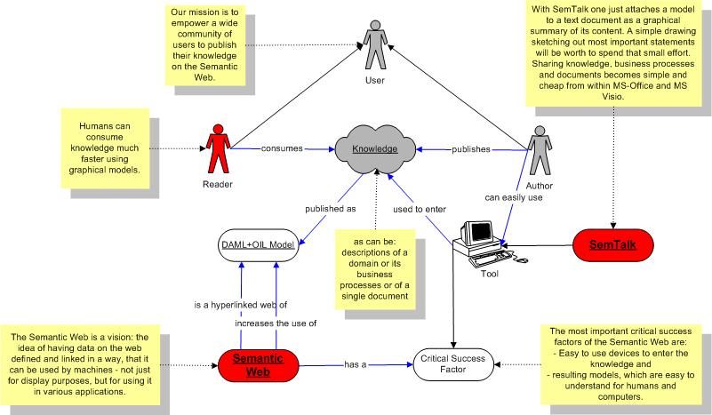
Figure 21. Semantic Web Ingredients (Berners-Lee, 2001).
XML-based markup languages provide a "unversal" storage and interchange format for web-distributed knowledge representation. Because information is stored in hierarchies, parsers can be easily written to validate and process large quantities of data. The ability to fuse information hierarchies is limited because the union of two trees may be best represented by a graph!!!!
The resource description framework (RDF) employs a graph data model to describe resourses that are directly and indirectly accessible via the Web. For example, a web page (or part of a web page) is a resource that is directly accessible. A person is a resource that might be indirectly accessible. The RDF data model is designed to be very general, which means that it is also very simple. The basic model contains just the concept of an assertion (e.g., a property of a resource), and the concept of a quotation -- that is, making assertions about assertions.
The useful functionality of the RDF data model comes from layers on top of RDF. To perform basic logic and reasoning we need, for example, definitions of vocabularies via ontology languages. We also need the ability to constrain the way in which data is used.
RDF schemas are web resources (that have URI's) that declare the existence of a new property and constraints on the way in which it can be used. RDF schemas are described in RDF. The key benefit in using RDF schemas to define ontologies (which in turn are written in RDF), is that all languages use the same data model. This simplifies interoperability of models.
The next layer is the logical layer. We need ways of writing logic into documents that will allow (among other things) for: (1) the checking of a document against a set of rules for self-consistency; (2) the deduction of one type of document from a document of another type; and (3) the resolution of a query by conversion of terms unknown to terms known (Berners-Lee, 1998). One such effort is the DAML+OIL model, an expressive web ontology language that is designed to describe the structure of a domain in terms of classes and objects (i.e., in object-oriented terms), and the formal rigor of an expressive description logic. DAML+OIL is the union of two efforts -- DAML is an acronym for the US DARPA Agent Markup Language (for details, see http://www.daml.org). OIL is an acronym for the Ontology Inference Layer (for details, see http://www.ontknowledge.org/oil).
In the DAML+OIL model, an ontology consists of a set of axioms that assert relationships between classes and objects. DAML+OIL classes can be names (i.e., URI's = universal resource index) or expressions. The expressive power of the language is determined by the class and property constructors, and axioms supported, The logical basis of the language means that reasoning services can be provided, both to support ontology design and to make DAML+OIL described web resources more accessible to automated processes (Horrocks, 2001).
Transfer of Semantic Web Technologies to Requirements Engineering
What is the minumum level of Semantic Web Technology that can mitigate (and hopefully overcome) limitations in present-day tools?
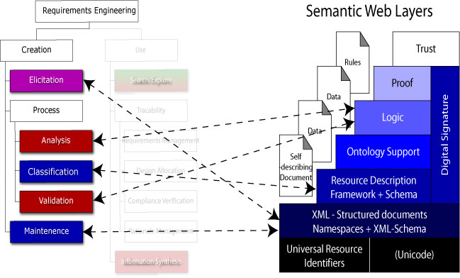
Figure 22. Requirements Engineering WBS (Create Branch) to Semantic Layer Cake (Selberg, 2002).
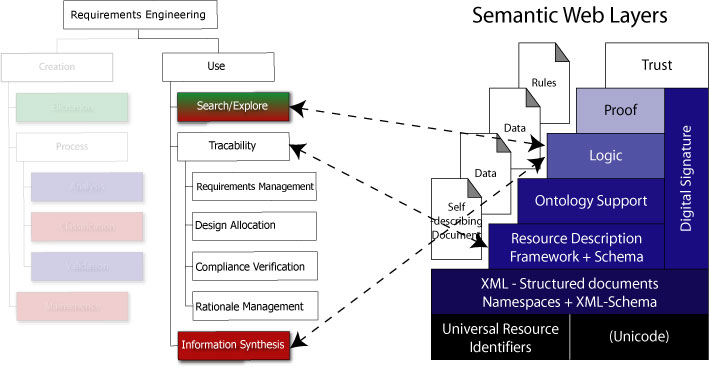
Figure 23. Requirements Engineering WBS (Use Branch) to Semantic Layer Cake (Selberg, 2002).
Anticipated Challenges and Trade-Offs in Design
In figuring out how "requirements engineering" methodologies and tools can benefit from Semantic Web technologies, it is likely that we have to deal to some interesting trade-offs in the capabilities of technologies:
A key question is: can we get the best of both worlds and apply these techniques to a new generation of "requirements engineering" tools?
Developed in February 2001 by Mark Austin
Copyright © 2001-2002, Mark Austin, University of Maryland