Research and Curriculum Development in Systems Engineering at UMCP

Presentation to Northrop Grumman, December 16, 2002

By: Mark Austin and Natasha Kositsyna (with help from Jeff Coriale)

Table of Contents Contact Information and Project Participants

  1. NSF-CRCD: Combined Research and Curriculum Development in Systems Engineering
    • Need for a Fresh Look at Systems Engineering
    • Major Challenges facing the Practicing Systems Engineer
    • Automation of Multidisciplinary Information-Based Design
  2. Curriculum Architecture and Deliverables
    • Key Technical Areas
    • University, Industry and Publishing Components of NSF-CRCD
    • Proposed Architecture for NSF-CRCD Materials
    • Case Study Framework and Relevant UML Diagrams
  3. Motivation and Mechanisms for Web-Based Systems Engineering
    • Mechanisms for Web-Based Systems Engineering Training
    • Annotating Diagrams with Use Case Pathways
    • Connecting Use-Case Pathways to Discipline-Specific Activities
  4. Research and Development Objectives
    • Near- and Medium-Term Objectives for Research and Software Development
    • Phase 1 : The JaDia Markup Language
    • Phase 1 : Simple Java-enabled Diagrams
    • Phase 2 : Click-and-Drop Editor for Java-Enabled Diagrams
  5. Opportunities for Joint Research, Development, and Education
    • Near-Term. Systems Engineering Tool Development
    • M.S. Thesis and Ph.D Research
    • Systems Engineering Education

Institute for Systems Research,
University of Maryland,
College Park, MD 20742.

Mark's e-mail: austin@isr.umd.edu
Natasha's e-mail: kosnat@isr.umd.edu
Jeff's e-mail: coriale@isr.umd.edu


UMD Project Participants: Mark Austin, John Baras, Bernie Frankpitt, Natasha Kositsyna, Vimal Mayank, Scott Selberg, Rajeshree Varangaonkar.

Students in the Master of Science in Systems Engineering (MSSE) program at UMD.


Current Industry Participants: Lockheed Martin, NASA Goddard Space Flight Center.


Need for a Fresh Look at Systems Engineering

Systems Engineering Research and Education at ISR

[System Scope]

Figure 1. What's Systems Engineering?

Our goals for Systems Engineering Research and Education at ISR are to formulate and provide formal (model-based) methodologies for "liason among disciplines" and "systems analysis and trade-off." Systems engineering activities complement (and support) those of the traditional engineering disciplines.

Student Population

We provide graduate-level systems engineering education for both students and practicing engineers.

  • MSSE (27): Full-time study leading to a first career position. Established in the Fall, 1987.
  • ENPM (23): Mid-career professionals looking to balance professional experience with academic training. Established in mid 1990s.

Age Profile. MSSE: 23-25; ENPM 27-32.

Why Systems Engineering is Important?

[Complex Systems] Over the past fifteen years there have been several important reasons and developments that have rendered systems engineering educational programs and methods critical. They are:

  1. Rapid changes in technology;

  2. Fast time-to-market most critical;

  3. Increasing pressure to lower costs;

  4. Increasing higher performance requirements;

  5. Increasing complexity of systems/products;

  6. Increased presence of embedded information and automation systems; and

  7. Failures due to lack of systems engineering.

70% of product and system failures are due to bad or no Systems Engineering effort, as our industry advisors (General Electric, Lockheed Martin, Northrop Grumman) and collaborators have frequently stated.

NSF CRCD Project Challenges

  1. Identify and address key research challenges facing "synthesis of engineering systems."

  2. How to codify this knowledge into courses and provide systematic methodologies and tools for the "synthesis of engineering systems?"

  3. How to find a practical way of using web technology to enhance: (a) classroom instruction, and (b) self-guided "post-training" instruction.


Major Challenges Facing the Practicing Systems Engineer

Support for Team Development

  • Teams of experts from multiple disciplines/domains working together on the solution of complex problems is a common requirement in industry today (e.g., integrated product teams (IPTs)). We need to maintain a shared view of the project objectives, and at the same time focus on specific tasks. See Figure 2.

    [System Concerns]

    Figure 2. Elements of Team-Based Development

  • A key challenge is avoiding communication and interpretation problems -- everyone needs to know what they are supposed to be working on, and when it's due!

Synthesis from Modular Components

  • The prevalence of synthesis from modular components is no longer true just for aerospace, defense and large government contracts (systems engineering started with Aerospace Engineering). Instead it is required in all commercial designs and operations. This so-called ``systems integration'' has become key and perhaps the most profitable engineering practice.

Growing Importance of Information-Driven Systems

  • In the past, systems have been seen from an operations point of view, where information and communications have been regarded as the supply of services necessary for the system to operate in pre-defined ways.
  • Nowadays, there is a rapidly evolving trend towards the team development of large-scale information-dominated systems, which exploit COTS and communications technologies, have superior performance and reliability, and are derived in response to various types of information drawn from a wide array of sources.

Large Volumes of Heterogeneous Data

  • Current and future data are in large volumes (not all relevant), numerically intensive (often requiring parallel algorithms for processing), multidimensional, heterogeneous, distributed, typically worked on specialized search engines, and represent multiple views (to the various users from engineering team members, to marketing, to sales people, to management, and to customers).


Our Strategy and Approach to Systems Engineering Practice

Promote use of Technology-Independent System-Level Design Representations

  • We want to create system-level design representation that are not tied to an underlying implementation technology. This can be achieved, in part, through separate representations for the logical and physical design.

    [Reuse Maturity's]

    Figure 3. Provision for Fomalization and Early Detection of Errors

  • Goal.
    Hardware and software implementations and specific technology selections are ``pushed'' near the very end (i.e., delayed as long as possible), but are performed once and must work flawlessly.

Promote Orthogonalization of Design Concerns -- Function-Architecture Co-Design

  • Emphasize function-architecture co-design. System design alternatives are created by mapping models of system behavior onto tentative system structures. System evaluation and ranking/optimization procedures eliminate the inferior solutions.

    [System Pathway2]

    Figure 4. Evaluation, Ranking, Optimization and Trade-Off Analysis for System Design Alternatives

  • In the design of complex engineering systems, "orthogonalization of concerns" simplifies the difficulty in exploring the space of design alternatives.

Promote Quantitative Procedures for System Evaluation, Optimization and Trade-Off

  • Develop sophisticated algorithmic, mathematical and quantitative methods implementable in modern software environments for system evaluation, ranking, optimization and trade-off analysis.

Promote Reuse at all levels of Abstraction

  • Abstract multiple disciplines to properly annotated information representations. This is the only way to allow communication among disciplines and multiple contextual views.

    [System Abstraction]

    Figure 5. Layers of Abstraction in Reuse

    A "general-purpose" information representation that can describe all aspects of system behavior and structure is currently unavailable. Hence, systems must work with multiple information abstractions. For example:

    • At a high-level of abstraction.
      Unified Modeling Language (UML), Technical drawings, Ontologies (Semantic Web).

    • At a lower-level of abstraction.
      Three dimensional geometric models, engineering simulation packages ... etc.

Promote Use of Object-Relational Database Storage

  • Enable reuse of designs, architectures and business processes through object-relational database storage.

    [NSF Proposal : Fig 1 ]

    Figure 6. Business Processes supported by Technology

  • Object-relational database storage can be the foundation for "platform-based design" of engineering systems.

Promote Automation for Multidisciplinary Information-Based Design

  • Systems engineers face several "major challenges" (e.g., synthesis of systems from modular components; support for team development in multi-national projects; growing importance of systems dominated by data/information).

  • We need to find ways to automate the capture and processing of data/information relevant to engineering system development.

    Figure 7. Requirements Engineering Processes supported by Semantic Web Technology

  • Systems engineering development processes (e.g., requirements engineering) and the Semamtic Web are both "chaotic systems-of-systems." Systems engineering methodologies and tools for automation can benefit from advances in Semamtic Web Technology!


Key Technical Areas

Key Technical Areas

  1. Object modeling of systems using the Unified Modeling Language (UML) and automation of model-based system behavior simulation.

  2. Semi-formal and formal languages for the representation of system requirements, system specifications, and allocation flowdown in heterogeneous (from the physical layer perspective) hierarchies.

  3. Object-relational databases and multiple views (engineering and others) of system data.

  4. Quantitative procedures for trade-off analysis when (mixed) Boolean and numeric variables are present.

  5. Validation and verification by quantitative treatment of tolerances and convex analysis.

Pathway from Research to Curriculum Development (as proposed in May, 2000)

[NSF Proposal : Fig 2 ]


University, Industry and Publishing Components of NSF-CRCD

Project Architecture for NSF CRCD (proposed in May, 2000)

[NSF Proposal : Fig 2 ]

Figure 8. University, Industry and Publishing components of NSF CRCD

Current Project Architecture (NSF, NASA Goddard, Lockheed Martin)

[Project Architecture]

Figure 9. Current Project Architecture (December, 2002)


Proposed Architecture for NSF CRCD Materials

Tutorials will be prepared in multiple formats and arranged into the following multi-layer architecture.

[CRCD Architecture]

Figure 10. Proposed Architecture for NSF CFCD Materials

Modules of slides will be prepared for each chapter of notes and case study. Chapter and case study material will be supported by lower-level case study examples, online material for UML notation and semantics, and so forth.


Case Study Framework and Relevant UML Diagrams

Case Study Framework

We would like all of our case studies to have a common system development and design framework:

  1. Problem Statement
  2. Generation of User Requirements
  3. Simplified Models of System Behavior
  4. Modeling the System Structure
  5. Creating the Logical Design
  6. Creating the Physical Design
  7. Evaluation and Ranking of System Design Alternatives
  8. System Optimization and Tradeoff Analysis
  9. Generalizing the Problem Domain for System Reuse
  10. References and Web Resources

Small Case Study Problems

Small case study problems will be developed by students in the MSSE program.

Classification of UML Diagrams

Major Area View Diagram
System Structure Static View Class Diagram
Use Case View Use Case Diagram
Implementation View Component Diagram
Deployment View Deployment Diagram
System Behavior State Machine View Statechart Diagram
Activity View Activity Diagram
Interaction View Sequence Diagram
Collaboration Diagram

Table 1. Classification of UML Diagrams for each Major Area

Tutorial and Case Study Support Material

Large Case Study Investigations

Larger case study investigations (and associated research) will be conducted in collaboration with US industry.


Mechanisms for Web-based Systems Engineering Training

Lessons Learned from Company ABC

  • Company ABC has in-house training for a sophisticated systems engineering tool. Training focuses on step-by-step procedures for using the tool to accomplish specific tasks.

  • At the end of the training, employees can use the tool to work through simple tasks, but have extreme difficulty in connecting high-level systems engineering (and organizational) processes to lower-level tasks.

Connecting High-level Processes to Lower-level Tasks

  • Employees need to see how high-level systems engineering (and organizational) processes are supported by tools.

    [Web Training : Fig 3 ]

  • How to make this connection? We need an expressive notation for bridging the gap between high-level learning objectives and systems engineering processes, and lower-level task- and tool-oriented procedures.

Lessons Learned from Company XYZ

What did we observe and learn from our training classes at XYZ?

  1. Systems engineering is a team activity -- training needs to support multiple viewpoints, levels of experience, and backgrounds.

  2. Systems engineering processes make use of many different entity types (e.g., primary and derived requirements; traceability links; various models of system behavior and system structure), sometimes connected in complicated ways.

  3. Training materials are linear -- but systems concepts are best organized into a variety of architectures. See the adjacent figure.

    [Web Training : Fig 4 ]

    Figure 11. Architecture of Training Material Contents

  4. Too many pages! Too many links! Readers feel overwhelmed. They jump around material and gloss over content rather than learning it.

  5. Students need to see how new systems engineering concepts can be applied to applications they are familiar with. (i.e., if you're at a company that makes trains, you need a case study on trains).

Challenge

  1. Need to find ways of using web technology to enhance quality of learning. Otherwise, whole exercise is a waste of time.


Annotating Diagrams with Use Case Pathways

Observations [signpost]

  • Opening a large folder of training materials for the first time is somewhat akin to your first visit to NYC -- it's intimidating. In both cases, it's easy to get lost unless you have a teacher, friend or map to guide you around.

  • Traditional media use the "table of contents" and "subject and author index" as guides.

  • If you don't have a friend to show you around NYC, it's a good idea to take a guided tour.

  • So why not create a similar mechanism for web-based training material?

Anatomy of a Lesson : Learning Objectives lead to Pathways across Diagrams

[NSF Proposal : Fig 2 ]

Features of a Good Guided Tour

  • The tour visits the most important parts of the city, and doesn't take too long.
  • Along the way, the tour guide brings "points of interest" to your attention.

Definition of a Use Case Pathway

  • A use case pathway is a wiggly line that enables a student to visualize scenarios threading through a system, without the scenarios being specified in great detail.

    [Definition of a Use Case Pathway ]

    Figure 12. Pathway Definition

  • Pathways will help students answer quenstions like: Where did I come from? Show me what to do now? What should I do next?

[NSF Proposal : Fig 2 ]

Figure 13. Adding Pathways to Tutorial Diagrams


Connecting Use Case Pathways to Discipline-Specific and Systems Engineering Activities

Use case pathways represent high-level system development processes.

[Usecase to Path ]

Mechanical and electrical engineers will deal with the lower-level details of implementation (i.e., sequences of tasks) in their own way.

Use Case Pathways <--> Traceability

Figure 14 shows the primary tracks of traceability for the development of a system-level product.

Figure 14. Traceability Mappings for the Development Pathway, Goals/Scenarios through Eystem Evaluation.

For system-level design, traceability begins with the connnection of goals and scenarios with use cases. It links the requirements and specifications with models of system behavior, system structure, and procedures for system evaluation.

Traceability can also be applied to the sequence of decisions defining the underlying development process, e.g., traceablity of rationale to specific decisions, decisions to actions items ...etc.


Near- and Medium-Term Research and Software Development

Phase 1 : Explore feasibility of XML to Java Applet Pathway (Sep't 1999 - August 2000)

  1. Design XML vocabulary, tag set structure for markup of diagrams and diagram pathways, and XML-to-Java source code compiler.

    [XML to Java Applet Development Pathway ]

    Figure 15. XML to Java Applet Pathway

Phase 2 : Develop Platform-Independent Diagram Editor (June, 2001 -- present)

  1. Create a click-and-drop editor for development of "Collections of Java-Enabled Diagrams." knowledge capture for systems engineering is enabled through:

    • Diagram annotation features,
    • Links to heterogenous data and information sources on the web, and
    • File and database storage.

    [Integrated Environment ]

    Figure 16. Tools and Technologies for Knowledge Capture in Systems Engineering

  2. We are currently working on the right-hand side of this diagram. Future versions of the editor will import of XML representations of diagrams, requirements, and systems stored in commerical databases (e.g., Oracle).

Phase 3 : Requirements Engineering Methodologies and Tools (April 2002 - present)

  1. Critical Assessment of Present-Day Systems Engineering Tools (e.g., DOORS and SLATE).

    How do we capture and represent knowledge through requirements engineering activities?

    Figure 17. Requirements Engineering Work Breakdown Structure (WBS).

    Figure 18. Requirements Engineering WBS and Industry Toolset Weakensses. (For details, see Ramesh and Jarke, 2001)

    Specific Limitations of Present-Day Tools (Selberg, 2002)

    1. Thick Descriptions.
      Current tools lack the ability to store informal representations (i.e., so-called thick descriptions) of systems conveying information along subtle or implied lines.

    2. Model Driven Trace Capture and Usage.
      Current tools lack mechansms for "easy linking" of models into the design environment (e.g., SLATE).

    3. Abstraction Mechanisms.
      Current tools lack the ability to search and explore requirements at various levels of abstraction.

    4. Inference Services.
      The lack of "inference services" in the work breakdown structure impacts the systems engineering process in several ways. Current tools are incapable of analyzing requirements for completeness or consistency. Search mechanisms are limited to keywords, which can be limiting for custom jargon in multidisciplinary and multilingual projects.

    Observations

    1. The glue that holds the system together is the basic modeling methodology.
    2. The loose coupling between knowlede domains and between CAD applications, and between knowledge repositories supports robust ad-hoc incremental development.
    3. Basic web-based infrastructure, which includes web-servers, application servers, and web browsers is already ubiquitous.

The Semantic Web Layer Cake

Figure 19. The Semantic Web Layer Cake (Berners-Lee, 2002).

The Semantic Web is an extension of the current web.

  1. It aims to give information a well-defined meaning, thereby creating a pathway for machine-to-machine communication and automated serives based on descriptions of semantics.

  2. XML files and web resources capture objects and classes. XML separates structure from presentation.

  3. RDF (resource description framework) describes relationships between objects and classes in a general but simple way. RDF separates content from structure, thereby allowing for the merging of multiple conceptual models.

  4. Ontologies provide a formal conceptualization (semantic representation) of a particular domain shared by a group of people.

  5. Ontology-based applications will be built on top of the Semantic Web infrastructure (i.e., XML, RDF and ontologies)

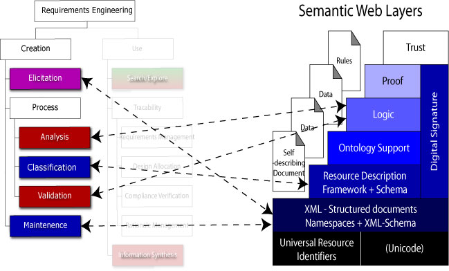
Transfer of Semantic Web Technologies to Tools for Requirments Engineering

What is the minimum level of Semantic Web Technology that can mitigate (and hopefully overcome) limitations in present-day tools?

Figure 20. Requirements Engineering WBS (Create Branch) to Semantic Layer Cake (Selberg, 2002).

Figure 21. Requirements Engineering WBS (Use Branch) to Semantic Layer Cake (Selberg, 2002).

References

  1. Ramesh B., and Jarke M., "Toward Reference Models for Requirements Traceability," IEEE Transactions on Software Engineering, Vol. 27., No. 1., January 2001, pp. 58-93.
  2. Selberg S., "Requirements Engineering and the Semantic Web," M.S. Thesis, Institute for Systems Research, University of Maryland, College Park, MD 20742, April 2002.


Overview of XML and Java Technology

Features and Benefits of XML

  • The eXtended markup language (XML) is a metalanguage -- that is, a language for describing other languages -- that allows people and computers to search for and exchange scientific, engineering and business data/information.

  • Web page content is separated from presentation -- applications decide how the data will be displayed.

    [XML-XSL ]

  • XML allows for custom interpretation of data sets (write once, publish anywhere).

Features and Benefits of Java

  • Java is an object-oriented programming language that compiles into a platform-independent bytecode.

  • Therefore, Java bytecode is portable, and we can reuse software components across heterogeneous computing platforms (write once, run anywhere).

XML Document to Application Pathway

[XML DOM Tree ]

Step-by-Step Development

  1. Design XML tagset and allowable hierarchy for combination of tags.
  2. Design a data type definition (DTD) file (or XML schema file).
  3. Create parser to transform XML document into (internal) tree structure.
  4. Develop application code to travserse tree structure and generate application-specific output (in our case, this will be Java source code).


Phase 1: The JaDia Markup Language

The JaDia Markup Language has 12 elements:

  1. <chart>

  2. <graph>

  3. <edge>

  4. <node>

  5. <frame>

  6. <framenode>

  7. <path>

  8. <pathedge>

  9. <link>

  10. <hint>

  11. <image>

  12. <text>

[NSF Proposal : XML elements ]

Figure 22. Components of the JaDia Markup Language


Screendumps of Drag-and-Drop Editor

[Natasha's editor ]

[Editor properties]

Figure 23. Drag-and-Drop Editor and Property Window

[Activity Diagram]

Figure 24. Activity Diagram (generated in editor)


Opportunities for Joint Research, Development, and Education

Near-Term Systems Engineering Tool Development

  1. Task 1.
    Generalize and implement pathways concepts to new applications (e.g., low-end traceability) and new tools (6 months work).
  2. Task 2.
    Design and implement XML/RDF schema for high-level system descriptions (i.e., networks of modules connected by ports and cables). (10 months work).
  3. Task 3.
    Develop software for file I/O of XML/RDF-based system descriptions (2 months work).

M.S. Thesis and Ph.D. Research.

  1. Task 1.
    Explore the extent to which AP 233 developments can be cast in a Semantic Web Framework. For example, using XML/RDF to write and manipulate text- and picture-based requirements (1 year for text-based requirements).
  2. Task 2.
    Explore application of Semantic Web Technologies to Synthesis and Automated Evaluation of System-Level Architectures (3 years work).
  3. Task 3.
    Create a framework for design and synthesis of systems from so-called "smart object" descriptions (3 years work).

    [Smart Objects]

    Figure 25. Framework for Smart Object Development

    Separate sections of each smart object contain knowledge of different aspects of the object's behavior.

    • Methods.
      The methods section contains knowledge of the behavior of the modeled element itself.
    • Interface.
      A interface section captures the description of the interaction of the object with the other "smart objects" in the system.
    • Monitor.
      The most unique portion of a smart object is the monitor section, which contains the control descriptions for the system as a whole, and for each individual object.

    Data about the state of the object is contained in the attributes section, along with rules which describe allowable values for the data, and actions to be taken automatically when the data is added, changed or accessed.

Near- and Medium-Term Systems Engineering Education

  1. Task 1.
    Reformat "small case studies" to take advantage of diagram technology. Test and evaluate the new material in academic and industry enviroments. Identify situations where "Java-enabled diagram technology" will add value to web-based systems engineering. Candidates include:

    • Step-by-step assembly procedures (e.g., for furniture assembly).
    • For signposting task-based models of design processes.

    We expect that both areas will employ combination of network and hierarchy system structures -- the Java-enabled diagram technology can handle this!

  2. Task 2.
    Work jointly with industry to create industry-sized case studies that can be weaved into system engineering training materials (1 year).
  3. Task 3.
    Store web-based training materials in databases (6 months work).


Print Version. December 14, 2002. [Left] [Up] [Right]