![[Complex Systems]](images/complexsystems.gif) Over the past fifteen years there have been several important reasons
and developments that have rendered systems engineering
methodologies, tools, and educational programs critical.
They are:
Over the past fifteen years there have been several important reasons
and developments that have rendered systems engineering
methodologies, tools, and educational programs critical.
They are:
|
By: Mark Austin (....with help from Natasha Kositsyna, Vimal Mayank, Scott Selberg) | |
| Table of Contents | Contact Information and Project Participants |
|
|
|
|
Institute for Systems Research, E-mail : austin@isr.umd.edu
Univ. of MD Project Participants:
Mark Austin, John Baras, Bernie Frankpitt,
Jim Hendler, Vimal Mayank, Natasha Kositsyna, Deep Saraf, Scott Selberg.
Industry Participants:
James Adams (Manager, Global Precipitation Measurement Group, NASA Goddard).
David Everett (Systems Engineer, NASA Goddard).
Michael Krok (GE Research and Development).
Paul Robitaille (Corporate Fellow, Lockheed Martin).
Sponsors:
National Science Foundation,
GE Research and Development,
Lockheed Martin,
Northrop Grumman,
NASA Goddard Space Flight Center.
In the pipeline:
Lockheed Martin Aerospace, Ft. Worth, TX.
|
Our Definition of Systems Engineering
Despite 30 years of history, systems engineering still means many things to many people (but, actually, the same is true of Civil Engineerin and it's been around for centuries). A few of the most commonly used texts contain at least 20-30 definitions of systems engineering. I happen to like:
At first this leads you to believe that "systems engineering is all things to all people," which of course runs the danger of delivering almost nothing to most.
To avoid falling into that trap, we are very explicit about what systems engineering means to us:
For this "working definition and vision" to be realized, we need methodologies for the synthesis of systems from modular components, support for team developments, ways to handles large volumes of heterogeneous data and, of cource, procedures for quantitative decision making.
The "front-end" part of our definition and focus is key because this is where decisions have the largest impact on commitment of funds in a project and, also, greatest opportunity for improvements.
Discipline Maturity
From a research and software development perspective, I think systems engineering is in exactly that same spot as finite elements, late 1960s. The problems aren't simple, but there are lots of opportunities for contributions.
Why Systems Engineering is Important?
Over the past fifteen years there have been several important reasons
and developments that have rendered systems engineering
methodologies, tools, and educational programs critical.
They are:
70% of product and system failures are due to bad or no Systems Engineering effort, as our industry advisors (General Electric, Lockheed Martin, Northrop Grumman) and collaborators have frequently stated.
![[Spacecraft Image1]](images/Satellite2.jpg)
Science Mission
Provide satellite coverage and sampling strategy to (Adams, 2001):
Systems Architecture
Form rain measuring constellation using co-op satellites from other programs suitable passive microwave radiometers dedicated to GPM mission:
![[Spacecraft Image1]](images/Satellite1.jpg)
Program Budget, Participants, and Schedule
GPM performance depends on sucessful partnerships -- space segment; ground segment; validation segment; research segment.
GPM Trade Space
The GPM trade space includes:
The NASA GPM project contains elements of the major challenges facing the practising systems engineer:
Support for Team Development
Today's industry requires that teams of experts from multiple disciplines/domains work together on the solution of complex problems (e.g., integrated product teams (IPTs)). These teams may be geographically dispersed and mobile.
We need to maintain a shared view of the project objectives, and at the same time focus on specific tasks. See Figure 2.
![[System Concerns]](images/system-concerns.gif)
Figure 1. Elements of Team-Based Development
A key challenge is avoiding communication and interpretation problems -- everyone needs to know what they are supposed to be working on, and when it's due!
Extended Project Duraation
In most large systems engineering projects, the team working on a project at its inception has probably retired before the project is completed.
Methodologies and tools are needed for the capture of knowledge (i.e., understanding of a problem domain; pathway of decision making) so that all is not lost when an employee leaves.
Synthesis from Modular Components
The prevalence of synthesis from modular components is no longer true just for aerospace, defense and large government contracts (systems engineering started with Aerospace Engineering). Instead it is required in all commercial designs and operations.
![[System decomposition, synthesis and reuse]](images/home-theatre1.gif)
Figure 2. Top-down decomposition and bottom-up synthesis coupled to reuse of objects/sub-systems.
This so-called ``systems integration'' has become key and perhaps the most profitable engineering practice.
Growing Importance of Information-Driven Systems
|
In the Past
Systems have been seen from an operations point of view, where information and communications have been regarded as the supply of services necessary for the system to operate in pre-defined ways. Nowadays There is a rapidly evolving trend towards the development of large-scale information-dominated systems, which exploit COTS and communications technologies, have superior performance and reliability, and are derived in response to various types of information drawn from a wide array of sources. Simply put -- these systems have functionality that would not be possible without an ability to gather and work with data/information. |
![[Car-Vintage]](images/Car-Vintage2.gif)
|
|
Example In a modern automobile, the electronics and communication systems account for 30% of the overall cost.
![[Car - Information]](images/Car-Information.jpg)
Figure 3. Electronics and Communications in a Modern Car. (Source: A.S. Sangiovanni-Vincentelli, EE 249, UC Berkeley, Fall 2002.) |
|
Large Volumes of Heterogeneous Data
Current and future data are in large volumes (not all relevant), numerically intensive (often requiring parallel algorithms for processing), multidimensional, heterogeneous, distributed, typically worked on specialized search engines, and represent multiple views (to the various users from engineering team members, to marketing, to sales people, to management, and to customers).
Example 1. Sensor Networks for NASA's GPM Project
Estimates of rainfall made in space need to be callibrated against Ground Station Measurements.
From Space
Dual frequency radar and multi-frequecy radiometer.
From Ground-Level
Rain Gauges
Example 2. Sensor Networks for Security of Buildings
Multiple sensor modalities must be used for the detection and classification of intruder and chemical/biological threats to a busy building. All sensors should be connected via a wireless network.
Information processing must be able to work with a variety of data formats:
Key research challenges include:
Systems engineering activities complement (and support) those of the traditional engineering disciplines.
![[System Scope]](images/system-scope.gif)
Figure 4. What's Systems Engineering?
Our goals for Systems Engineering Research and Education at ISR are to formulate and provide formal (model-based) methodologies for "liason among disciplines" and "systems analysis and trade-off."
Economic Considerations
![[Knowledge Gap]](images/knowledge-gap.gif)
Figure 5. So-called "Knowledge Gap" in Systems Development
Importance of Frontend Development
![[Knowledge Gap]](images/knowledge-gap2.gif)
Figure 6. Desired Goal for Improved Design Flexibility
Research Challenges
We promote:
Use of Technology-Independent System-Level Design Representations
![[Reuse Maturity's]](images/reuse-maturity2.gif)
Enhanced Systems Engineering Management through Design/Requirements Representations Connected by Mappings and Traceability
Figure 8. Traceability Mappings for the Development Pathway, Goals/Scenarios through Eystem Evaluation.
For system-level design, traceability begins with the connnection of goals and scenarios with use cases. It links the requirements and specifications with models of system behavior, system structure, and procedures for system evaluation.
Management of Complexity through Orthogonalization of Design Concerns
![[System Pathway2]](images/system-pathway2.gif)
Figure 9. Evaluation, Ranking, Optimization and Trade-Off Analysis for System Design Alternatives
Quantitative Procedures for System Evaluation, Optimization and Trade-Off
Automation for Multidisciplinary Information-Based Design
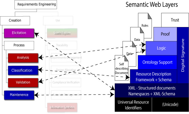
Figure 10. Requirements Engineering Processes supported by Semantic Web Technology
Reuse at All Levels of Abstraction
![[System Abstraction]](images/system-abstraction.gif)
A "general-purpose" information representation that can describe all aspects of system behavior and structure is currently unavailable. Hence, systems must work with multiple information abstractions. For example:
| |
|
|
|
Use of Object-Relational Database Storage
![[NSF Proposal : Fig 1 ]](images/proposal-fig1.gif)
Figure 12. Business Processes supported by Technology
Elements of Requirements Engineering
Requirements engineering bridges the gap between organizational-level and project-level concerns.
Figure 13. Requirements Bridge the Gap between Organization- and Project-Level Development.
Requirements engineering addresses the development and validation of methods for eliciting, representing, analyzing, and confirming system requirements and with methods for transforming requirements into specifications for design and implementation.
Figure 14. Components of the Requirements Engineering Process
How do we capture and represent knowledge through requirements engineering activities?
Problem Size and Complexity
There are a plethora of examples:
The only economically feasible approach to managing this complexity is by automating parts of the reasoning process with inference services.
Writing Requirements and Specifications
Requirements and specifications need to be written in a manner that balances two key aspects: (1) they should be readable, and (2) they should lend themselves to various forms of automated processing.
Table 1 summarizes the key features of requirements and specifications.
| |
|
| Initial requirements are informal, incomplete, and often ambiguous .... | Specifications are based upon a detailed knowledge of a product and its (required or established) capabilities... |
|
The system should .... The system must .... |
Requirements and capabilities:
|
|
|
| Validation of requirements supported by traceability to specifications and design subsystems/objects. | Verification of specifications supported by formal testing procedures, numerical simulations of system behavior, experiments in the lab ... etc. |
Table 1. Comparison of Requirements and Specifications
Low-End Models of Product and Process Traceability
Product Traceability
Product traceability mechanisms connect requirements to elements of the design.
Figure 15. Components of the Requirements Engineering Process
Two key questions need to be answered:
Requirements-to-design traceability ensures that the design takes all of the requirements into account. Design-to-requirements traceability ensures that design elements are actually needed.
Process Traceability
Traceability can also be applied to the
sequence of decisions defining the underlying development process,
e.g., traceablity of rationale to specific decisions,
decisions to actions items ...etc.
State-of-the-Art Capability for Requirements Management Tools (e.g., DOORS and SLATE).
Organizing requirements into the right structure can help:
Telelogic DOORS (...used across GE businesses; LM Aerospace)
Telelogic DOORS is an Enterprise requirements managment system.
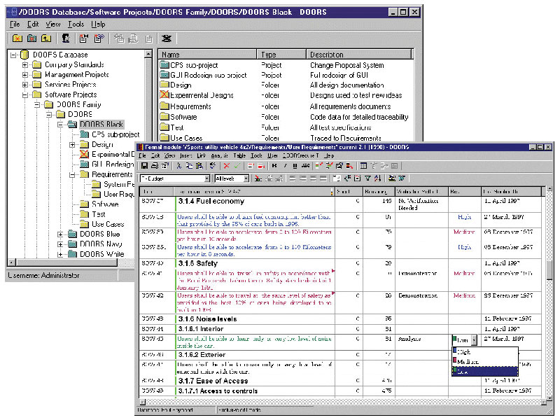
Figure 16. Representation of Requirements in DOORS
DOORS does not explicitly support system viewpoints.
Case Study Application: Lockheed Martin Aerospace, Ft. Worth, TX
Joint Strike Fighter Project. 30 year duration. Budget $200 Billion.
Lockheed is unveiling a new, four-pronged architecture:
SLATE (System Level Tool for Enterprises) (...used by NASA Goddard; Northrop Grumman)
An application is modeled as a network of connected requirements and design abstraction hierarchies.
Traceablity Links and Translational Mappings (TRAMs)
|
|
Relationships define connectivity between requirements and abstraction blocks in the design hierarchy.
Translational Mappings (TRAMs) define relationships between different system abstraction block hierarchies. TRAMs allow for cause-and-effect relationships among "design disciplines" to be modeled.
Sample Screendumps
Example 1. A screen of requirements ....
Figure 17. Representation of Requirements in SLATE.
Example 1. An abstraction block hierarchy with translational mappings among (TRAMs) viewpoints.
Figure 18. Representation of Abstraction Block Hierarchy and Translational Mappings (TRAMs) in SLATE.
Critical Assessment of Present-Day Systems Engineering Tools (e.g., DOORS and SLATE).
Lessons Learned from Industry
Specific Limitations of Present-Day Tools (Selberg, 2002)
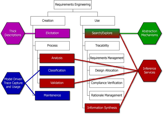
Figure 19. Requirements Engineering WBS and Industry Toolset Weakensses. (For details, see Ramesh and Jarke, 2001)
System of Systems
![[Systems of systems]](images/sos-diagram.gif)
A system of systems is a collection of independently useful systems which have been glued together to achieve further emergent properties.
The primary design focus is on the interfaces, specifically the communication standards, as very little can be done to modify the monolithic systems (Selberg, 2000).
Management and Communication Styles for System-of-Systems
There are three management styles which influence the communication style: coerced (directed), collaborative, and chaotic (virtual) (Maier, 1999; Maier, 2000).
In a coerced, or directed, system of systems there is a central entity which can dictate behavior.
Example -- Windows Operating System
The Windows Operating System dictates certain behaviors of the software applications that run under it.
A collaborative system of system is composed of several systems working together for synergistic effects.
Example -- Transportation Services at an Airport
![[Collaborative SoS]](images/sos-definition.gif)
Here the "taxi" and "airplane" systems work together to provide a chain of services neither could provide by themselves. Airports provide the appropriate interfaces to these systems.
Chaotic (or virtual) systems of systems have no management structure.
Examples -- The Internet and Open Source Software Development
The Internet operates only on recommended standards which the various systems voluntarily adopt.
![[Collaborative SoS]](images/sos-linux-penguin.gif)
![[Collaborative SoS]](images/sos-www.gif)
Chaotic systems of systems work because the various systems find the interface standards to be advantageous. Companies build web pages which adhere to the HTML standard not because they have to, but because it is economically advantageous to.
Requirements Engineering
Monolithic Model of Requirements Engineering
A requirements management system, one which is concerned with the creation and use of the requirements for a given project, can be implemented as a monolithic system.
Chaotic System of Systems Model of Requirements Engineering
But as soon as the need to leverage or reuse the requirements across projects, companies, and industries is found, a monolithic system approach is no longer viable.
![[SoS Requirements]](images/sos-requirements.gif)
The chaotic system of systems is a more appropriate model because every project, company, and industry will operate based on personal needs and desires. Thus, an open standard is needed which will allow the various systems to share a common data structure and build customized tools to meet the personal needs.
Research Approach
These are very similar tasks faced by the Internet. It is therefore a reasonable approach to compare the needs of a requirements engineering system to the Internet and look for solutions along parallel lines of thought.
Objectives of the Semantic Web
The Semantic Web is an extension of the current web. It aims to:
Modeling
The Semantic Web Layer Cake
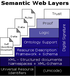
Figure 20. The Semantic Web Layer Cake (Berners-Lee, 2002). |
The Semantic Web is an extension of the current web.
|
Simple Example (... for how things will eventually work)
Today's search engines rely on "keywords."
![[System Rules]](images/system-rules.gif)
Suppose that we could represent facts on the web.
     Fact 1.  John and Mary are married.
     Fact 2.  Jane's best friend is Mary.
And suppose that the (ontology) conceptualization of this domain tells us:
     Concept 1.  If "a" is married to "b" then "a and b are friends"
     Concept 2.  If "a" and "b" are "best friends" then "a" then "b" are friends.
     Concept 3.  If "a" is a friend of "b" then "b" is a friend of "a."
With these facts and concepts in place, a semantic search engine should be able to accept queries of the type:
Query 1. Who are Mary's friends?
and answer with:
Answer. John and Jane.
Note. Concepts limit the "design space" by placing constraints around the set of (potentially) feasible solutions (c.f., differential equations in engineering).
Key Observation
Transfer of Semantic Web Technologies to Tools for Requirements Engineering
What is the minimum level of Semantic Web Technology that can mitigate (and hopefully overcome) limitations in present-day tools?
Figure 21. Requirements Engineering WBS (Create Branch) to Semantic Layer Cake (Selberg, 2002).
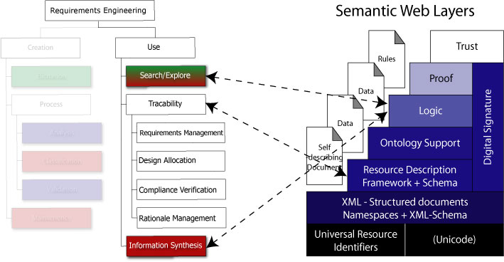
Figure 22. Requirements Engineering WBS (Use Branch) to Semantic Layer Cake (Selberg, 2002).
Anticipated Challenges and Trade-Offs in Design
In figuring out how "requirements engineering" methodologies and tools can benefit from Semantic Web technologies, it is likely that we have to deal to some interesting trade-offs in the capabilities of technologies:
A key question is: can we get the best of both worlds and apply these techniques to a new generation of "requirements engineering" tools?
Figure 23. Advancing Requirements Engineering with Semantic Web Technologies.
Participants: Natasha Kositsyna, Mark Austin.
Support: NSF, Northrop Grumman, GE Research and Development.
Motivation -- Lessons Learned from Training Classes at Company XYZ (in 1999-2000)
Ideally, systems engineering training activities should mirror those of the practising systems engineer. This is hard!!!
![[Web Training : Fig 4 ]](images/web-training-fig4.gif)
Figure 24. Architecture of Training Material Contents
Challenge
We need to find ways of using web technology to enhance quality of learning.
Otherwise, whole exercise is a waste of time.
XML Document to Application Pathway
The eXtended markup language (XML) is a metalanguage -- that is, a language for describing other languages -- that allows people and computers to search for and exchange scientific, engineering and business data/information.
![[XML DOM Tree ]](images/xml-domtree.gif)
Phase 1. Explore feasibility of XML to Java Applet Pathway (Sep't 1999 - August 2000)
Design XML vocabulary, tag set structure for markup of diagrams and diagram pathways, and XML-to-Java source code compiler.
![[XML to Java Applet Development Pathway ]](images/xml-to-java.gif)
Figure 25. XML to Java Applet Pathway
The step-by-step development procedures is as follows:
|
JaDia Markup Language The JaDia Markup Language has 12 elements:
|
![[NSF Proposal : XML elements ]](images/xml-elements.gif)
Figure 26. Components of the JaDia Markup Language |
Phase 2 : Develop Platform-Independent Diagram Editor (June, 2001 -- present)
Create a click-and-drop editor for development of "Collections of Java-Enabled Diagrams." knowledge capture for systems engineering is enabled through:
![[Integrated Environment ]](images/digspecs.jpg)
We are currently working on the right-hand side of this diagram. Future versions of the editor will import of XML representations of diagrams, requirements, and systems stored in commerical databases (e.g., Oracle).
Screendumps from Drag-and-Drop Editor
![[Natasha's editor ]](images/editor.jpg)
Figure 28. Drag-and-Drop Editor and Property Window
Participants: Scott Selberg, Mark Austin.
Problem Statement
State-of-the-Art Systems Engineering tools have graphical user interfaces that are very poorly designed and nonintuitive. Systems engineers should be able to look at trees of requiremnts and engineering schematics and indenify mapping and traceability relations among them.
The purpose of this project is to explore the extent to which XML and RDF technologies (i.e., SVG, Javascript, cascading stylesheets) can improve the human-computer interface.
XML Separates Content from Presentation
The eXtended markup language (XML) is a metalanguage -- that is, a language for describing other languages -- that allows people and computers to search for and exchange scientific, engineering and business data/information.
Web page content is separated from presentation -- applications decide how the data will be displayed.
![[XML-XSL ]](images/xml-xsl.gif)
Figure 29. XML Portability Model
XML allows for custom interpretation of data sets (write once, publish anywhere).
Traceability Viewer Model
![[Traceability Viewer]](images/traceability-viewer-model.jpg)
Figure 30. Traceability Viewer Model
XML/RDF Datafile for Requirements
As an example, the top level requirement, Time Reference, is shown below.
<?xml version="1.0"?>
<?xml-stylesheet type="text/xsl" href="requirement.xsl"?>

<requirement id="TimeReference.req.xml"
        xmlns:="http://www.isr.umd.edu/~selberg"
        xmlns:rdf="http://www.w3.org/1999/02/22-rdf-syntax-ns#">

    <description>
        A physical device which displays a signal at regular frequency.
    </description>

    <need>
        For a performing musician it can often be difficult to sustain a constant
        beat.  This is especially true when the music is complex, or very slow
        and sustained.  A physical time reference allows the musician to train
        his or her internal clock to a higher degree of precision.
    </need>

    <rdf:RDF>
    <rdf:Description about="TimeReference.req.xml">
        <refined_by>
            <rdf:Description about="AuditorySignal.req.xml"/>
            <rdf:Description about="AdjustableFrequency.req.xml"/>
        </refined_by>
        <satisfied_by>
            <rdf:Description about="Metronome.com.xml"/>
        </satisfied_by>
    </rdf:Description>
    </rdf:RDF>

    <history>
       <entry timestamp="12:38:03 PM 3/2/02">
              Created Requirement
       </entry>
    </history>
</requirement>
Notice that each of the basic categories (i.e., not the RDF links) simply contain text. The RDF section is the core of the linking. The rdf:Description block identifies the subject of the RDF statement. Beneath it are two property arcs: refined_by and satisfied_by. These arcs then point to the subject objects.
Requirements Traceability for Design of a Metronome
![[Traceability Viewer]](images/traceability-viewer3.gif)
Figure 31. Requirements Traceability for Design of a Metronome
Participants: Vimal Mayank, Mark Austin, Natasha Kositsyna, Dave Everett (NASA Goddard)
Support: NSF, NASA Goddard Space Flight Center.
Project Objectives
Methodologies for the team development of system-level architectures need to support the following activities:
The purpose of this project is to develop methodologies and tools for the synthesis, management, and visualization of system-level architectures likely to be found in the NASA Global Precipitation Measurement (GPM) project. The research and development will leverage advances in the Semantic Web.
Two Simple Examples
We view system architectures as collections of modules, connectors, and rules for system assembly.
![[Architectural Graph1]](images/system-graph1.gif)
Figure 32. Synthesis of System Architectures Supported by Product Descriptions on Web
More complicated subsystems will be modeled graphs.
![[Architectural Graph1]](images/system-graph2.gif)
Figure 33. Simplified Assembly of System Architectures via Merging of Graphs.
We need to be able to merge graph models and remove inconsistencies among viewpoints.
Study Problem -- Architecture-Level Synthesis and Analysis of a Home Theatre System
We would like to create and interactive design environment where the specifications for components are found on the web.
![[Architecture2]](images/system-architecture2.gif)
Figure 34. Synthesis of System Architectures Supported by Product Descriptions on Web
Figure 34 shows a simple scenario:
A system design tool should:
Top-Down System-Level Development Coupled with Component Reuse
Design Goal
I need a home theatre system.
Operations Concept
Our wishes are very modest -- we will simply
watch movies on a large size theatre screen and high fidelity audio system.
![[Requirements to Architecture]](images/system-reuse2.gif)
Figure 35. Flowdown of Requirements to a Detailed System Architecture Description.
Pathway from High-Level Requirements to Component-Level Requirements
| |
||||||||||||||||||||
|
PRELIMINARY AGREEMENT BETWEEN CUSTOMER AND BUILDER
|
||||||||||||||||||||
| |
||||||||||||||||||||
|
DETAILED AGREEMENT BETWEEN CUSTOMER AND BUILDER
Visual Display
Audio System
Implicit Requirements
|
||||||||||||||||||||
| |
||||||||||||||||||||
|
COMPONENT REQUIREMENTS
Flatscreen TV
Amplifier System
Speaker System
|
||||||||||||||||||||
Research questions to be answered:
Representation of System Architecture
The system architecture is the structure of the pieces that make up a system, including the resposibilities of the pieces and their interconnection.
Research questions to be answered:
System Structure
Here is a first-cut implementation of entities making up the system structure.
![[UML Model of System Architecture]](images/final02-fig2.gif)
Figure 36. UML Model of the System Architecture.
Port capability -- services required and services provided -- is described by an interface specification.
Port Model
And here is a preliminary port model.
![[UML Model of System Architecture]](images/final02-fig4.gif)
Figure 37. UML Model of Ports, Port Connectors, and Port Geometry.
Bottom-up Implementation of the System (without trade-off among subsystem attributes).
To start with, let's assume that trade-off of attributes (e.g., cost) among the system components does not occur. The step-by-step implementation might proceed as follows:
Step 1. Selection of the Amplifier.
![[Step 1. Implementation of Architecture]](images/system-reuse4.gif)
Figure 38. Assembly of the System Architecture. Choosing the Amplifier.
Step 2. Selection of the Speakers.
![[Step 2. Implementation of Architecture]](images/system-reuse5.gif)
Figure 39. Assembly of the System Architecture. Choosing the Speakers.
Bottom-up Implementation of the System (with trade-off)
Step 1. Selection of the Amplifier.
![[Step 1. Implementation of Architecture]](images/system-reuse6.gif)
Figure 40. Assembly of the System Architecture. Choosing the Speakers.
Step 2. Selection of the Speakers.
![[Step 2. Implementation of Architecture]](images/system-reuse7.gif)
Figure 41. Assembly of the System Architecture. Choosing the Speakers.
Semi-Formal Representation for Requirements
We assume that "some requirements" can be expressed in a template format. For example:
    The
        <subject>
    of the
        <object>
    shall be
        <constraintt>.
The requirement:
The "price" of the "amplifier system" shall be < US $400.00
The corresponding markup in XML might look like:
    <requirement>
        <template>    1 </template>
        <subject> price </subject>
        <object> amplifier system </object>
        <constraint>
            <mathML>
                less than 400
            </mathML>
        </constraint>
    </requirement>
Attaching Specifications to Objects/Components
An object-specification pair defines a set of behaviors can be offered by a component/object.
![[Elements of an Object-Specification Pair]](images/system-reuse3.gif)
Figure 42. Elements of an Object-Specification Pair.
Object/component descriptions must be at least multi-input multi-output (MIMO). Otherwise they aren't useful.
Research
Research questions to be answered:
Logical Checking of Requirements
Issue:
Proposed Solution:
Simple Example: Connecting a Digital Camera to a Computer
![[Home-Theatre1.gif]](images/home-theatre2.gif)
Figure 43. Synthesis of System Assemblies Accompanied by Logical Checking of Requirements.
Requirements:
Complexity and System Levels
Issue:
Proposed Solution:
Ensuring Consistency Across Different System Viewpoints
Issue:
Proposed Solution:
![[Home-Theatre1.gif]](images/home-theatre3.gif)
Figure 44. Viewpoints of a Home Theatre System.
Expected Benefits
Conclusion
Further Issues .....
But we still need to:
Important Applications ...
Figure 45. Version 0.0001 of our Sensor Network Layout Editor. (April, 2003)
(Source: Vijay Krishnamuthy, MSSE Student)
|
Copyright © 2003, Mark Austin, University of Maryland. |
![[Left]](images/button-left.gif)
![[Up]](images/button-up.gif)
![[Right]](images/button-right.gif)
|