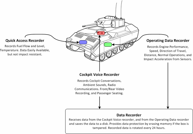
Figure 1: Layout of the Black Box Design
 ENES 489P Projects, Fall Semester, 2010
[ Project 1 ]: Black Box Design
[ Project 2 ]: Security of Wireless Sensor Networks
[ Project 3 ]: Systems Engineering Microfluidic Devices for Cell Separation
Title: Black Box Design
Team Members: Ahmad Asi, Benjimin Chang, Mehdi Dadfarnia, Serge Kamta, Ifzalul Khan
Abstract: A black box design should include both a vehicle data recorder and also a voice and visual recorder so that an incident can be accurately reconstructed from the vehicle's status and visual recordings.
This particular design will allow analysts to determine whether the cause of the incident was a vehicle error, operating error, or environmental factors. This design is similar to Flight Data Recorder and Cockpit Voice Recorder with the addition of a similar On-Board Diagnostics (OBD) II design in modern automotive vehicles. A typical black box should have the capability to withstand 3400g and temperatures up to 1000oC.

Figure 1: Layout of the Black Box Design
The basic functions of a black box should include continuous audio/visual recording for both the front and rear of the vehicle. This will be part of the voice and visual recorder. Because this design must withstand 3400g in the event of an incident, a typical disk drive will not suffice. A 512 GB solid-state drive (SSD) (approx $2000) has the capability to withstand 1500g and provide enough space to record at least 24 hours of audio and video at 640x480@15 FPS with voice quality audio. In order for the SSD to withstand 3400g padding and springs can provide shock resistance to the disk and a mirroring redundancy will be designated for fault tolerance.
The second part of the black box is the vehicle data recorder including the status of the vehicle (vehicle speed, engine health, ...), environmental status (outside temperature, climate), and passenger seating arrangement. Pressure sensors will be used to determine where each passenger is seated, and the number of passengers in the vehicle. Pressure sensors will also be placed on the chassis of the vehicle in order to determine the location of the incident if an explosion, or side/head-on collision are to occur. GPS and time/date data will also be recorded in order to determine the location of the incident.
The recorded data will be rotated every 24 hours in order to provide continuous recording without having to replace the drive. Wireless communication can also be used in order to provide vehicle monitoring with a monitoring station. As part of this design, tamper resistance is crucial to this design. Memory can be wiped when the case is open, or if the device is not attached to a module. During normal operation, a module is attached to the vehicle. This module contains a signature unique to the vehicle. When the vehicle is destroyed, the module will also be destroyed. In order to access the data, a module with the same signature must also be attached to the black box, otherwise the device will return null data. If the black box is opened, fuses in the SSD will break the connection thus destroying the data. This way when retrieving the data, and the operator forgets to plug in the module, the data will not be destroyed as the operator should not need to open the box.
Class Presentation: Scheduled for December X.
Title: Security of Wireless Sensor Networks
Team Members: Jeremy Prince, Brad Klein, Brian Wang, and Kaustubh Jain
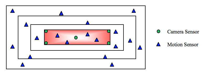
Abstract: We will build a wireless sensor network to track intruders and monitor the security area shown in the adjacent figure.

Both camera sensors and motion sensors will be needed. Motion sensors are deployed in the whole area we are interested, and video/camera sensors are only deployed in the security area.
The interested area is divided into layers for the sake of energy efficiency. Sensors in the outmost layer are always in the ON mode, while other sensors are in the low-power mode by default. When an intruder enters the outmost layer, sensors in this layer will begin to track him/her. Before the intruder enters the inner layer, sensors around his/her location in the inner layer will be notified to wake up by the sensors in the outer layer. Then sensors in the outer layer will enter the low-power mode. The case is similar if the intruder moves from a inner layer to an outer layer.
When the intruder enters the security area, a camera sensor which is responsible to monitor the sub-area around the intruder's location will also be woken up to take a picture. When the intruder moves to another sub-area, another camera sensor will be woken up and this one will enter the low-power mode.
Class Presentation: Scheduled for December X.
Title: Systems Engineering Microfluidic Devices for Cell Separation
Team Members: Jeffrey Misiewicz and Bao Nguyen
Abstract: Systems engineering is an effective tool in modeling many different types of processes. It can be used to simplify complex biological systems, for example, by defining their sub-systems, requirements, constraints, and the relationship between them. The following system seeks to describe how a microfluidic device can be simulated to separate specific cells based on their charge.

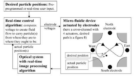
An experiment carried out by Dr. Benjamin Shapiro describes such system, in which actuated electrodes were utilized to control and direct the movement of one or many particles along a set path. A polydimethylsiloxane (PDMS) microfluidic device provides a foundation in which particle steering can occur. The channels can be arranged in a cross formation as seen in the figure below. The microfluidic device is coupled with a feedback system that utilizes electroosmotic forces to guide the particles. Their position is monitored by an optical system that determines and processes their real time location using a control algorithm. This in turn activates an appropriate electrode, creating a flow field to direct the particle to their proper location.
Using tools such as Modelica in conjunction with MagicDraw, the flow pattern and control loop can be modeled and analyzed at a systems level. The particle steering system is dependent on the flow subsystem, which in turn contains inputs of channel geometry and feedback control. The geometry can be further broken down into shape, size, and channel pattern components. Likewise, the feedback control depends on the optical system, algorithm, and the electrode signal. Control and geometry subsystems can therefore be considered the constraints because the optimization of these components dictates effective particle steering
Last Modified: October 20, 2010.
Copyright © 2010, Institute for Systems Research, University of Maryland