 Structural Analysis of Moment-Resistant Frame
 Structural Analysis of Moment-Resistant Frame
[ Problem Statement ]
[ Finite Element Mesh ]
[ Displacements ]
[ Bending Moments and Shear Forces ]
[ Reactions ]
[ Input/Output Files ]
You will need Aladdin 2.0 to run this problem.
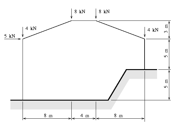
Figure [1] is an elevation view of a planar moment resistant frame, which is part of an industrial building constructed on a hill-side.

The building frame has width 20 m, and a total height of 13 m. It is constructed from steel sections having moment of inertia I = 6.6 x 10^8 mm^4 and cross section area A = 4.26 x 10^4 mm^2. The steel material has modulus of elasticity E = 200 GPa.
The building frame is subject to gravity loads, plus a moderate wind loading. We will assume that the gravity loads can be represented by point loads of 20 kN distributed over joints 2 through 4, and wind loadings can be represented by a single lateral point load of 5 kN applied to joint 2.
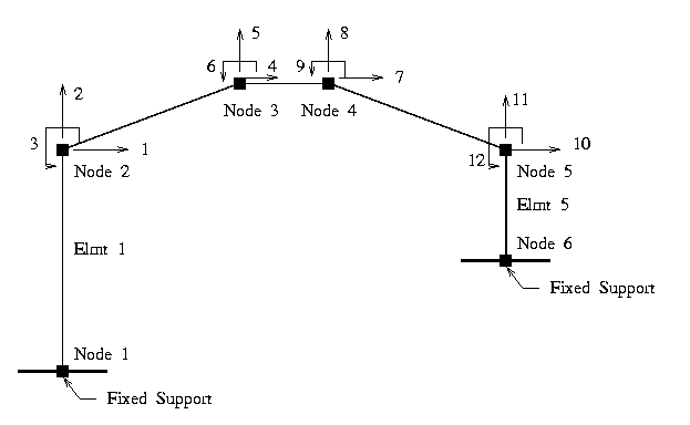
The building will be modeled with six nodes/joints and five beam-column elements, as labeled in Figure [2].

The building supports at nodes 1 and 5 are fully fixed in their translational and rotational degrees of freedom. Nodes 2 through 5 will each be modeled with 2 unknown translational displacements and one unknown rotation. This means that the overall building behavior will be characterized by twelve degrees of freedom.
The block of code:
   node = 1;
   AddNode( node, [  0 m,  0 m ] );
   node = 2;
   AddNode( node, [  0 m, 10 m ] );
   node = 3;
   AddNode( node, [  8 m, 13 m ] );
   node = 4;
   AddNode( node, [ 12 m, 13 m ] );
   node = 5;
   AddNode( node, [ 20 m, 10 m ] );
   node = 6;
   AddNode( node, [ 20 m,  5 m ] );
adds the five nodes to the Aladdin database. A simple looping construct:
   elmtno = 0;
   for ( ii = 1; ii <= 5 ; ii = ii + 1 ) {
       elmtno = elmtno + 1;
       AddElmt( elmtno, [ elmtno , elmtno + 1 ], "mrfelmt");
   }
can now be used to attach finite elements to the nodes.
Section and Material Properties
The section and material properties are:
   ElementAttr("mrfelmt") { type     = "FRAME_2D";
                            section  = "mrfsection";
                            material = "mrfmaterial";
                           }

   SectionAttr("mrfsection") { Izz       = 6.60e8 mm^4;
                               Iyy       = 6.60e8 mm^4;
                               area      = 4.26e4 mm^2;
                             }

   MaterialAttr("mrfmaterial") { poisson = 0.25;
                                 yield   = 275 MPa;
                                 E       = 200 GPa;
                               }
Boundary Conditions
The block of code:
    nodeno = 1;
    FixNode( nodeno, [ 1, 1, 1 ]);
    nodeno = 6;
    FixNode( nodeno, [ 1, 1, 1 ]);
applies full-fixity to the left- and right-hand supports (i.e., nodes 1 and 6, respectively).
External Loads
The abbreviated block of code:
    nodeno = 2;
    NodeLoad( nodeno, [ 5 kN, -4 kN, 0.0 N*m ]);
demonstrates the procedure for specifying external loads -- in this case, the external loads at node 2 are:
    Horizontal Force Fx =  5.0 kN,
    Vertical   Force Fy = -4.0 kN,
    Applied Moment   Mz =  0.0 N*m.
Once the global stiffness and external load matrices have been formed with:
    stiff = Stiff();
    eload = ExternalLoad();
the frame displacements can be computed and printed with:
    displ = Solve(stiff, eload);
    PrintDispl(displ);
The nodal displacements are:
    ============================================================
     Node                           Displacement
       No            displ-x           displ-y             rot-z
    ============================================================
     units                m                 m               rad
       1         0.00000e+00       0.00000e+00       0.00000e+00
       2        -1.66648e-03      -1.39108e-05      -1.29048e-04
       3        -5.38502e-04      -3.05289e-03      -2.32416e-04
       4        -5.42568e-04      -2.97523e-03       2.68259e-04
       5         5.58718e-04      -7.12911e-06       4.99272e-05
       6         0.00000e+00       0.00000e+00       0.00000e+00
The command:
PrintStress(displ);
prints the bending moments and axial forces acting on each beam element. The distribution of bending moments is summarized in Figure [3].

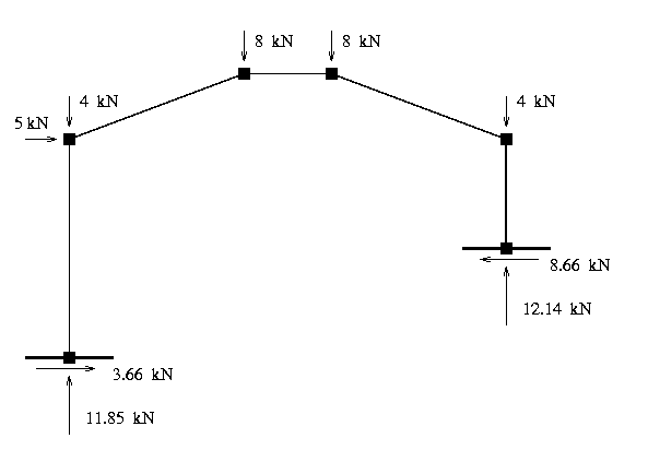
Figure [4] shows the external loads and support reactions.

Support Reactions
The command:
actions = GetStress( [1], displ );
retrieves a two by five matrix, actions, containing the x- and y- coordinates of the element nodes, and the horizontal and vertical forces, and moment, acting on each node -- that is:
    MATRIX : "actions"

    row/col                  1            2            3            4            5
            units            m            m            N            N          N.m
       1            0.00000e+00  0.00000e+00  1.18520e+04 -3.66177e+03 -1.66054e+04
       2            0.00000e+00  1.00000e+01 -1.18520e+04  3.66177e+03 -2.00123e+04
The block of commands:
    print "\n";
    print "Left-hand Support Reactions\n";
    print "===========================\n\n";

    print "  Vertical Reaction = ",  actions[1][3]   (kN), "\n";
    print "Horizontal Reaction = ", -actions[1][4]   (kN), "\n";
    print "    Moment Reaction = ",  actions[1][5] (kN*m), "\n";
extracts the relevant element forces, and generates information on the support reactions:
    Left-hand Support Reactions
    ===========================

      Vertical Reaction =      11.85 kN
    Horizontal Reaction =      3.662 kN
        Moment Reaction =     -16.61 kN.m
Of course a similar block of commands can be used to compute and print the right-hand support reactions.
Equilibrium Check
The accuracy of the analysis can be checked by making sure the sum of the column actions -- that is, elements 1 and 5 -- is balanced by the sum of external loads. in the horizontal direction we have:
    ===============================================================
    External Forces                         Shear Forces in Columns
    ===============================================================

    Joint 2    5,000.0  N
    Joint 3        0.0  N
    Joint 4        0.0  N                    Element 1  -3,661.8  N
    Joint 5        0.0  N                    Element 5   8,661.8  N
    ===============================================================
    Total      5,000.0  N                                5,000.0  N
    ===============================================================
And in the vertical direction we have:
    ===============================================================
    External Forces                          Axial Force in Columns
    ===============================================================

    Joint 2    -4,000.0  N
    Joint 3    -8,000.0  N
    Joint 4    -8,000.0  N                  Element 1  -11,852.0  N
    Joint 5    -4,000.0  N                  Element 5  -12,148.0  N
    ===============================================================
    Total     -20,000.0  N                             -20,000.0  N
    ===============================================================