
CHBE446 Project 1 - Solar home dehumidification systemOur capstone design project for Spring 2016 is motivated by Team Maryland's participation in the 2017 Solar Decathlon. This project will be the focus of this class up to and potentially through spring break; a follow-on or entirely different project will finish out the semester. |

|
Project motivation
Both the 2007 LEAFHouse and the 2011 WaterShed University of Maryland entries to the U.S. Department of Energy Solar Decathlon used unique sorption-based dehumidification systems to control indoor relative humidity. The key component in each design was a hygroscopic aqueous solution that absorbed water from the house interior air; this sorbent, enriched with the water from the house interior, was regenerated using solar energy to heat and drive out the absorbed water. The regenerated desiccant then was cooled and returned to the house interior to complete the sorption circuit. The LEAFHouse system was based on an aqueous calcium chloride (CaCl2) solution, while WaterShed used a lithium chloride (LiCl) solution.
We will initially focus on the LiCl system; our design activities will include conceptual and detailed process design, consideration of design alternatives, energy integration, process optimization, assessment of safety and environmental impact, and dynamic simulation of the complete system.
Project basis (Part 1)
As of 10 February 2016, the project functional requirements are:
- The house containing the dehumidification system (DS) shall be home to a family of four.
- The house containing the DS shall be located in the College Park, MD region.
- The house shall have an interior floor area of 900 ft2.
- The house shall have an interior ceiling height of 10 ft.
- The DS primary power input shall be the sun.
- The DS backup-up power shall be provided by the home electrical system.
- The DS shall not affect indoor chemical air quality.
- The DS shall not emit any substance but water to the outdoor environment.
- The DS shall be able to function automatically.
- The DS shall maintain an indoor relative humidity of 60% or less.
- The DS shall have a life expectancy of 15 years.
- The DS shall require service intervals of one year or greater.
- The DS shall bring the house indoor relative humidity to its specified value within 10 minutes.
Project use cases (Part 1)
- The house is unoccupied during a summer day; fresh outside air is cooled to the indoor temperature, raising the indoor relative humidity (RH). At 5pm, a house occupant enters and the dehumidifier starts, bringing the indoor RH to its specified value in the required time.
- A person typically emits 800 ml/day of water (liquid equivalent) during normal respiration and perspiration. You have decided to have a party, 39 guests show up, and the house must maintain a specified indoor RH.
- The pitch of your house's roof is such that solar panels mounted flat to the roof surface are tilted 39 oS. The date is the fall equinox, it is a sunny day, and it is solar noon - assume this results in the sun's rays being normal to the panel surface with an irradiance of 1 kW/m2. The PV panels (for generating electrical power, not for solar thermal) are 20% efficient.
-
Calculations more refined than the previous Use Case predict the following, time-dependent irradiance for our tilted roof:
The family enters the house at 3pm, finding the indoor temperature at 72 deg. F and 90% RH. During the next hour, the family emits water vapor according to Use Case 2, plus an additional 0.1 mol s-1 due to showering and cooking. 36 guests show up at 4pm and stay until 8pm.time 6 7 8 9 10 11 12 13 14 15 16 17 18 irradiance, kW m-2 0 0.2 0.46 0.7 0.89 1.0 1.04 1.0 0.88 0.7 0.46 0.2 0
VLE concept of operation
To start, we will examine the VLE behavior of the LiCl/water system; a comprehensive source of LiCl and CaCl2 solution property data can be found at:
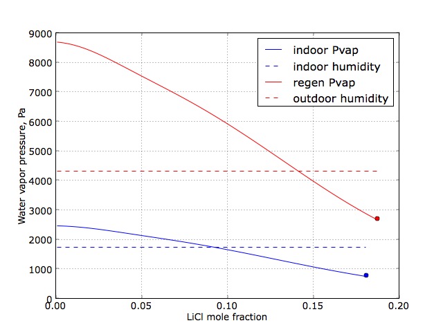
The figure above illustrates the change in equilibrium water vapor pressure as a function of desiccant solution LiCl mole fraction (x) for the desiccant solution at room temperature (blue solid curve) and at an elevated temperature (red solid curve). The first is relevant to the design of the absorber - the interior process in which room air is dehumidified. To determine the required LiCl concentration, we also plot the room relative humidity (dashed blue line), translated into water vapor partial pressure. In the low LiCl concentration range, the desiccant solution water vapor pressure exceeds the room humidity value, and so the system would increase room humidity under these conditions. However, for x ~> 0.1, the solution vapor pressure is less than the room humidity level; the difference in partial pressures provides the driving force for the absorption process. We note that the blue curve ends at the point where the solution becomes saturated with LiCl (marked by the blue dot).
The enriched (with respect to water) desiccant solution then is regenerated by increasing its temperature using solar energy. Shown in red, the difference between the water vapor pressure (solid curve) and the outdoor air (dashed line) water vapor partial pressures must be positive to regenerate the desiccant; if negative, the desiccant would absorb water vapor from the outside air, clearly an undesirable mode of operation.
Basic project flowsheet
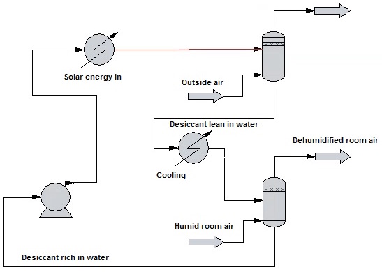
As can be seen in the simplified process flow diagram shown below, the home dehumidification system constitutes a very traditional chemical engineering gas purification process, with room air being stripped of water vapor in the absorption "column," enriched sorbent pumped and heated before being stripped of the absorbed water in the regeneration column. The lean solvent then is cooled and returned to the absorber.
Individual report 1.1
Write a short individual report and submit through ELMS the following:
- Convert project requirements to SI units listed on the CHBE 446 homepage.
- What ChemCAD thermodynamics package is appropriate for LiCl/water VLE?
- Develop a procedure to compute equilibrium water vapor pressure as a function of temperature and LiCl desiccant solution mole fraction.
- Using the computational procedure you developed, create a plot similar to the VLE diagram above corresponding to an indoor temperature and relative humidity of 72 deg. F and 60%, respectively, and outdoor temperature and relative humidity of 85 deg. F and 80%, and a regenerator operating temperature of 105 deg. F.
- Are there any patents covering the process?
Group report 1.2
Preliminary absorber and regenerator designs based on your group's best VLE property prediction method developed in subproject 1.1. Assume room and outdoor conditions are the same as in problem 1.1.
-
Using your VLE software (not ChemCAD) and assuming the absorber and regenerators are single-stage equilibrium processes,
- Determine the range of feasible operation with respect to mole fraction of the lean LiCl solution as it enters the absorber; describe what happens at the limits of operation and plot the rate of water removal from the house air between those limits (mol/s per mol/s of LiCl in the lean LiCl solution), assuming an infinitely large house.
- Plot solar power requirement (W per mol/s LiCl in the lean LiCl stream) over the range of operation.
- What is the maximum rate of water removal possible by this system?
- Compare the results found above with ChemCAD simulations.
Group report 1.3
Single-stage absorber/regenerator design refinement and identification of realistic operating conditions.
- Survey the literature to assess the upper temperature limit that is possible for heating fluids with non-concentrating solar power for residential applications. This will become your upper temperature limit on the rich desiccant fed to the regenerator.
- Survey the HVAC literature to determine recommended air-flow rates and room air turnover times to justify a maximum limit on air flow rate to the absorber.
- Starting with Ch 20 of Towler and Sinnott and then moving on to other references, develop a correlation that predicts air blower power requirements as a function of outlet pressure and air flow rate.
- Consider Use Case 1: Is is possible for your design to satisfy the requirements associated with this Use Case?
Group report 1.4
Energy integration, detailed energy balance analysis.
- The WaterShed house used a glycol solution as a working fluid in the solar thermal collector system. Modify your dehumidifier design to reflect this change and set the glycol temperature entering the glycol/rich desiccant heat exchanger to the maximum temperature that can be produced in your solar thermal system. Summarize the changes in the context of Use Case 2.
- What are the energy integration opportunities in this system? Modify your design accordingly, and summarize your results in the context of Use Case 2.
- Quantify fan power requirements for your design in the context of Use Case 2.
- Assess the benefits of using multistage equilibrium absorber and regenerator units for Use Case 2.
- Compare the previous calculations to a ChemCAD simulation.
Group report 1.5
Safety and solar issues- Assess the safety of your current desiccant system design; do not include any speculative or unjustified safety issues.
- Assess the environmental impact of your design; again, include only information that can be cited and/or quantified.
- Design your working fluid solar heater according to Use Case 3. Likewise, determine PV panel area required to power the system electrical power requirements.
- What are the corrosion issues associated with your design? Summarize materials of construction for critical components.
- Model and quantify the rate of production of liquid desiccant droplets that would be carried out with the air streams of both the absorber and regenerator.
Group report 1.6
Full dynamic simulation in the context of Use Case 4.- Derive the modeling differential/algebraic equations describing the time-dependent room air water vapor content assuming the desiccant system operates in quasi-equilibrium relative to the changes in room air.
- Propose a control system that regulates room air relative humidity by manipulating room air flow to the absorber, keeping LiCl solution flow rate constant.
- Tune your control system and simulate the room air response to Use Case 4; be sure to report the time of day when you dehumidifier must switch to a battery storage system or utility grid electrical power.
- Survey commercially available indoor relative humidity sensors that are appropriate for our system.
- Design and implement (if possible) a control system for the rich desiccant solar heating system.
Group presentation 1
Time limit: 6 minutes with 2 minutes for questions and transitions- Use readable text and figures.
- Do not spend time on motivation: concentrate on your specific design choices and novel aspects of your design.
- Slide 1: Team and members
- Slides 2 and 3: Specifics regarding your primary model of the dehumidification system thermodynamics and material balance model elements
- Slide 4: Clearly tabulated nominal operating conditions including desiccant flow rate, air flows, water removal rate, system temperatures, etc. Roof area covered by your solar power collection systems.
- Slide 5: A graphical representation of Use Case 4
- Slide 6: A graphical representation of your system response to UC 4
- Safety issues associated with your process
- Environmental impact of your process
- Unique aspects of your process
- Design elements, energy efficiency, any other important engineering aspects of your design
Midterm quiz
Closed book and notes; no computers although calculators will be required.The objective of this quiz is to make sure each team member is aware of all essential elements of the project. Specific topics expected to be on the quiz include
- Given a simplified water vapor/liquid desiccant VLE relationship (e.g., a K-value evaluated at a specific set of operating conditions), determine the outlet stream molar flow rates and compositions for single equilibrium stages corresponding to the absorber and regenerator
- Knowing only the solar energy concepts presented in this class, compute the area required for the solar collector to heat the (water) rich desiccant stream prior to the regenerator
- Be able to perform the computations necessary to determine the area of a counter-current heat exchanger used to preheat the rich desiccant prior to solar heating, a unit that may have been used in your design resulting from the energy integration process
- Be able to substantively outline the safety and environmental impact of your design
- Be able to do basic computations including those related to relative humidity (RH) and determining the time it would take for the solar desiccant system to reduce the room RH given a dehumidification system water removal rate (will require material balance, linear ODE solution methods)
- Describe the elements of your control system including controlled and manipulated variables, control system gains, etc.
Group final report 1.7
Page limit: 5 not including title page, references, and appendices.-
The title page includes the project title, team number, team members, member contributions to the overall project, date, honor pledge, and project executive summary.
- The executive summary should summarize in one paragraph the major design features, the role of solar energy, and your team's unequivocal opinion on whether this is a viable technology.
- As stated on the CHBE446 main page, the main body of the report must be limited to five pages. It is basically a compilation of the previous interim reports.
- Include any additional information can be included in the report Appendix, however, the main body of the report must be self-contained with sufficient quantitative information and representative calculations to make a convincing argument for the validity of your design and conclusions.
- Content of the final report main body should roughly follow the presentation.
Individual report 2.1
This initial individual report consists of background information relevant to comparing current H2 production to solar-powered electrolysis processes. What is due is a concise, highly referenced document of 2-4 pages; the report should address the following topics:- Cite one or more current estimates of domestic H2 annual production rate, reported in Mmoles/year (106 moles/year) and tons/year
- What are the primary domestic uses for the H2 produced?
- Briefly outline the feedstocks, the reaction chemistry, typical process operating conditions (e.g., T and P in K, Pa, resp.), and catalysts used for the current major routes to domestic H2 production
- List typical H2 plant sizes in terms of annual production rates (Mmoles/year)
- Given the feedstock information above, present a table that lists the feedstock and product prices in terms of USD/Mmole
Group report 2.2
ChemCAD H2 plant simulation- Use the in-class assignment as the starting point for both the ChemCAD design and the group report 2.2
- Be sure to review the report guidelines described on the CHBE 446 home page
- Describe your rationale for the ChemCAD reactor choices made by your team
- Team size will be factored into the report grade
Group report 2.3
H2 process design refinement and process economics- Using simple, but justifiable, reaction rate expressions for the steam reforming and WGS reactors, determine the reactor vessel size and the catalyst loading for each
- Determine the capital and operating costs for the overall process
- Determine the profit/106 moles of H2 based on a 20 year plant life, a decommissioning cost equal to 50% of the original capital cost, a 7% interest rate, straight-line depreciation, and a tax rate of 25%
- Present details on your energy integration approach
- Describe how levelized cost for electricity is computed in the context of solar energy.
Group presentation 2
Time limit: 6 minutes with 2 minutes for questions and transitions- Use readable text and figures.
- Do not spend time on motivation: concentrate on your specific design choices and novel aspects of your design.
- Slide 1: Team and members
- Slides 2 and 3: Flow sheet, clearly tabulated primary process flow rates and compositions, and nominal reactor and separator operating conditions
- Slide 4: Catalyst and sorbent (if any) loadings
- Slides 5 and 6: Process economic analysis, including profit/106 moles H2
- Slides 7 and 8: Electrolysis process design and economic analysis
- Slide 9: Economic comparison between H2 production processes - at what value of levelized electricity cost to the two approaches become equal?